





 President’s Message
Blog
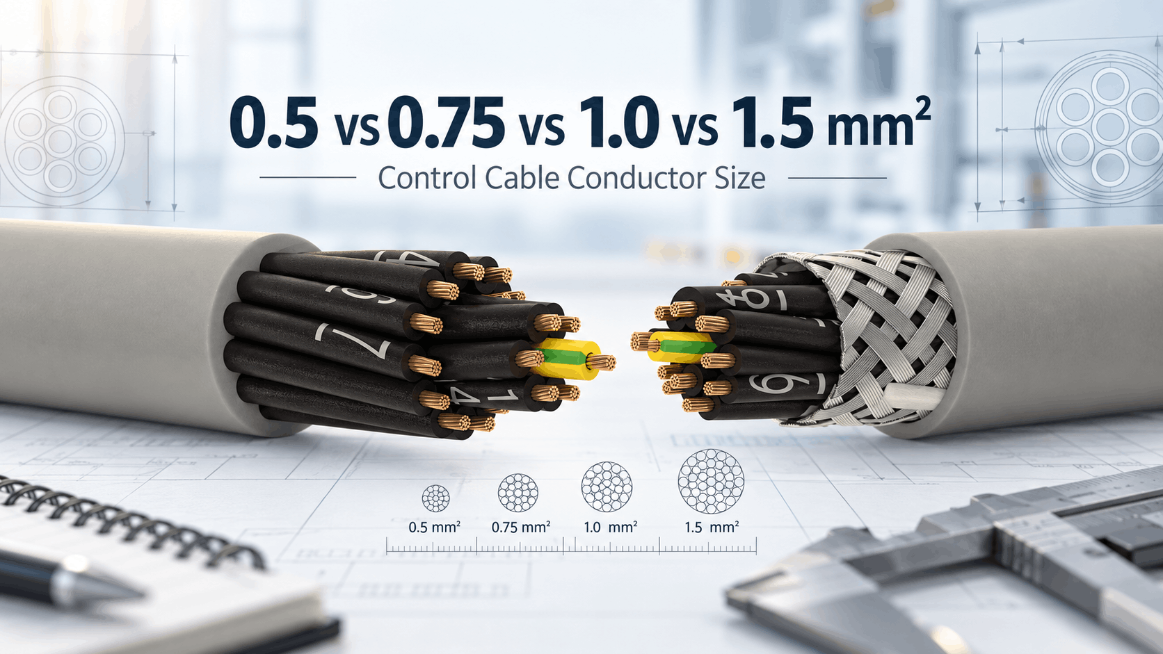
0.5 vs 0.75 vs 1.0 vs 1.5 mm² Control Cable: How to Select Conductor Size
Reading Time: 18 minutes
Control cable conductor size affects resistance, voltage drop, current-carrying capability, cable diameter, flexibility and cost. Among flexible industrial control cables, 0.5 mm², 0.75 mm², 1.0 mm² and 1.5 mm² are some of the most frequently specified conductor cross-sections.
However, choosing the largest size is not automatically the best engineering decision. A 1.5 mm² conductor provides lower resistance and greater current capability than 0.5 mm², but it also increases cable diameter, copper weight, bending stiffness and terminal-space requirements.
Likewise, choosing 0.5 mm² simply because the circuit carries only a small current can be a mistake when the cable run is long. Conductor resistance accumulates with distance, so voltage drop can become significant even in relatively low-current 24 VDC control circuits.
Therefore, engineers should select conductor size from the combination of current, route length, permitted voltage drop, ambient temperature, installation method, terminal capacity and mechanical requirements.
Quick answer: 0.5 mm² is often suitable for low-current control, signal and short automation circuits. 0.75 mm² provides additional current and voltage-drop margin while remaining compact. 1.0 mm² is a versatile general-purpose control-cable size for many industrial applications. 1.5 mm² becomes attractive for higher-current auxiliary circuits, longer runs or applications where lower conductor resistance is important. Nevertheless, the final size must be verified against the actual cable datasheet and applicable installation requirements.
Control Cable Conductor Size at a Glance
| Conductor Size | Max. Class 5 Copper Resistance at 20°C | Relative Resistance | Typical Selection Logic |
|---|---|---|---|
| 0.5 mm² | 39.0 Ω/km | Highest | Low-current, short control and signal circuits |
| 0.75 mm² | 26.0 Ω/km | Moderate-high | General controls requiring additional margin |
| 1.0 mm² | 19.5 Ω/km | Moderate | Versatile industrial control and auxiliary circuits |
| 1.5 mm² | 13.3 Ω/km | Lowest of the four | Higher current, longer routes and lower voltage drop |
Consequently, doubling the conductor cross-section does not merely change cable size. It significantly reduces circuit resistance.
What Does Control Cable Conductor Size Mean?
Control cable conductor size is normally expressed as the nominal cross-sectional area of each copper conductor in square millimetres.
For example:
- 0.5 mm²
- 0.75 mm²
- 1.0 mm²
- 1.5 mm²
The value represents conductor cross-section rather than cable diameter.
This distinction is important because flexible conductors contain multiple fine copper strands. Therefore, a 1.0 mm² Class 5 conductor is not one solid copper wire with a simple 1.0 mm² visible profile.
Instead, the total copper cross-section of the strands corresponds to the nominal conductor size according to the applicable conductor standard.
IEC 60228 and Control Cable Conductor Size
IEC 60228 defines standardized conductor cross-sections and maximum conductor resistance values for many insulated cable constructions.
Flexible industrial control cables commonly use Class 5 copper conductors.
For Class 5 bare copper conductors, typical maximum resistance values at 20°C are:
| Cross-Section | Maximum Resistance at 20°C |
|---|---|
| 0.5 mm² | 39.0 Ω/km |
| 0.75 mm² | 26.0 Ω/km |
| 1.0 mm² | 19.5 Ω/km |
| 1.5 mm² | 13.3 Ω/km |
These resistance values demonstrate why conductor size matters even when the electrical load appears small.
As conductor cross-section increases, resistance decreases substantially.
0.5 vs 0.75 vs 1.0 vs 1.5 mm²: The Main Difference
The core difference between these conductor sizes is the amount of copper available to carry current.
A larger conductor provides:
- Lower electrical resistance
- Lower voltage drop
- Lower resistive heating for the same current
- Greater current-carrying potential
- More electrical margin on long routes
However, increasing conductor size can also result in:
- Larger cable diameter
- Higher cable weight
- More copper consumption
- Higher material cost
- Reduced flexibility
- Larger gland requirements
- Greater terminal-space requirements
Therefore, conductor selection is an optimization problem rather than a simple rule that bigger is always better.
How Resistance Changes with Control Cable Conductor Size
Resistance provides one of the clearest comparisons between conductor sizes.
Using the standard Class 5 copper resistance values:
A 0.5 mm² conductor has a maximum resistance of approximately 39.0 Ω/km at 20°C.
Increasing the cross-section to 0.75 mm² reduces this figure to 26.0 Ω/km.
At 1.0 mm², resistance falls to 19.5 Ω/km.
Meanwhile, 1.5 mm² reduces resistance further to 13.3 Ω/km.
Consequently, a 1.5 mm² conductor has roughly one-third the resistance of a 0.5 mm² conductor over the same length.
Why Resistance Matters in Control Circuits
Electrical resistance produces two important effects:
- Voltage drop
- Heat generation
Voltage drop can prevent a remote device from receiving sufficient operating voltage.
Resistive heating, meanwhile, increases according to the current flowing through the conductor.
Therefore, conductor selection must consider both the current and the total circuit length.
A short low-current circuit may operate perfectly with 0.5 mm², while the same load located much farther away can require 0.75, 1.0 or 1.5 mm².
Control Cable Conductor Size and Voltage Drop
Voltage drop is particularly important in 24 VDC automation systems because even a few volts can represent a meaningful percentage of the available supply voltage.
A simplified DC voltage-drop relationship is:
Voltage drop = Current × Loop resistance
The loop includes both outgoing and returning conductors.
Therefore, a device located 100 metres from the control panel can create approximately 200 metres of total copper path in a two-wire circuit.
Why Cable Length Can Change the Required Size
Consider two identical devices drawing the same current.
One device is located 10 metres from the control panel.
The other is located 150 metres away.
Even though the loads are identical, the second circuit contains fifteen times more conductor length.
As a result, conductor resistance and voltage drop become much greater.
Therefore, the correct control cable conductor size can change solely because of cable-route length.
Illustrative Voltage Drop Comparison
The following example demonstrates the relative effect of conductor resistance.
Assume a 100 m one-way route using a two-conductor DC circuit. The total loop length is approximately 200 m.
| Conductor Size | Approx. Loop Resistance at 20°C | Voltage Drop at 0.1 A |
|---|---|---|
| 0.5 mm² | 7.8 Ω | 0.78 V |
| 0.75 mm² | 5.2 Ω | 0.52 V |
| 1.0 mm² | 3.9 Ω | 0.39 V |
| 1.5 mm² | 2.66 Ω | 0.27 V |
These values illustrate conductor resistance only and should not replace a complete engineering calculation.
Nevertheless, the comparison clearly shows why larger conductors provide greater voltage-drop margin on long circuits.
Control Cable Conductor Size for 24 VDC Systems
Modern industrial automation relies heavily on 24 VDC equipment.
Typical devices include:
- PLC inputs and outputs
- Proximity sensors
- Photoelectric sensors
- Relays
- Solenoid valves
- Actuators
- Control modules
Many individual devices draw relatively small currents.
Therefore, 0.5 mm² can provide sufficient current capacity for short circuits.
However, long routes can make voltage drop the limiting factor before thermal current capacity becomes a concern.
For this reason, engineers often move toward 0.75 mm², 1.0 mm² or 1.5 mm² as cable length or load current increases.
When 0.5 mm² Control Cable Makes Sense
0.5 mm² represents a compact and economical conductor size for many industrial control circuits.
Potential applications include:
- PLC digital inputs
- Low-current sensors
- Relay feedback circuits
- Status signals
- Short 24 VDC control connections
- Low-current monitoring circuits
The smaller conductor can help reduce overall cable diameter, especially in multicore cables containing many conductors.
Therefore, 0.5 mm² becomes attractive where panel space and cable flexibility matter.
However, route length and voltage drop must still be checked.
Advantages of 0.5 mm² Control Cable
Compared with larger conductor sizes, 0.5 mm² can provide:
- Smaller outside diameter
- Lower copper weight
- Greater flexibility
- Smaller cable glands
- Easier routing in crowded panels
- Lower material cost
These advantages become particularly significant in high-core-count control cables.
For example, increasing forty conductors from 0.5 mm² to 1.5 mm² can materially increase the overall cable diameter and weight.
Limitations of 0.5 mm² Control Cable
The primary limitation is higher conductor resistance.
At 39.0 Ω/km for Class 5 copper at 20°C, long routes can produce significant voltage drop.
Furthermore, smaller conductors provide less current-carrying capability than larger cross-sections.
Therefore, 0.5 mm² should not be selected simply because the connected device is categorized as “control equipment.”
The actual current and cable length still matter.
When 0.75 mm² Control Cable Makes Sense
0.75 mm² offers a useful middle ground between compact 0.5 mm² cable and larger general-purpose constructions.
Its maximum Class 5 conductor resistance drops to approximately 26.0 Ω/km at 20°C.
This represents a substantial improvement over 0.5 mm² while maintaining relatively compact cable dimensions.
Consequently, 0.75 mm² is often attractive for:
- 24 VDC automation circuits
- Small solenoid valves
- Relay coils
- Actuator control
- Moderate-length control runs
- General machine wiring
0.5 vs 0.75 mm² Control Cable
The move from 0.5 to 0.75 mm² increases conductor cross-section by 50%.
At the same time, maximum conductor resistance falls from 39.0 to 26.0 Ω/km.
This reduction can provide meaningful voltage-drop improvement without the larger dimensional increase associated with moving directly to 1.5 mm².
Therefore, 0.75 mm² can be a useful optimization where 0.5 mm² provides insufficient electrical margin but compact cable construction remains important.
When 1.0 mm² Control Cable Makes Sense
1.0 mm² is a highly versatile control cable conductor size for industrial machinery and automation.
Its Class 5 resistance is approximately 19.5 Ω/km at 20°C.
Potential applications include:
- General machine-control circuits
- Auxiliary power circuits
- Contactors and relays
- Solenoid valves
- Motor-control auxiliary wiring
- Longer 24 VDC runs
- Control-panel interconnections
The size provides substantially lower resistance than 0.5 or 0.75 mm² while remaining relatively manageable in multicore constructions.
Therefore, 1.0 mm² can serve as a practical general-purpose choice when engineers want additional electrical margin without moving to 1.5 mm².
0.75 vs 1.0 mm² Control Cable
The electrical improvement from 0.75 to 1.0 mm² is smaller than the move from 0.5 to 0.75 mm², but it remains meaningful.
Resistance decreases from 26.0 to 19.5 Ω/km.
That corresponds to approximately 25% lower conductor resistance.
Consequently, 1.0 mm² can provide better voltage-drop performance on longer routes while still maintaining reasonable flexibility.
When 1.5 mm² Control Cable Makes Sense
Among the four sizes compared here, 1.5 mm² provides the lowest conductor resistance and the strongest current-carrying potential.
Class 5 copper resistance falls to approximately 13.3 Ω/km at 20°C.
This makes 1.5 mm² particularly attractive for:
- Higher-current auxiliary circuits
- Long 24 VDC control runs
- Solenoid and actuator circuits with higher power demand
- Control transformers and auxiliary feeds where appropriate
- Industrial circuits requiring additional voltage-drop margin
- Projects standardized around 1.5 mm² minimum wiring
However, the larger conductor increases cable diameter, copper weight and bending stiffness.
Therefore, using 1.5 mm² for every low-current PLC circuit can create unnecessary bulk.
1.0 vs 1.5 mm² Control Cable
Moving from 1.0 to 1.5 mm² increases copper cross-section by 50%.
Maximum Class 5 resistance decreases from 19.5 to 13.3 Ω/km.
As a result, longer circuits experience less voltage drop for the same current.
Nevertheless, the mechanical trade-off becomes more noticeable than at smaller conductor sizes.
In high-core-count cables, 1.5 mm² can create a significantly larger and heavier overall product.
Control Cable Conductor Size and Current Capacity
Current-carrying capacity increases as conductor cross-section increases, but engineers should avoid using one universal amperage table for every control cable.
Ampacity depends on more than copper area.
Important factors include:
- Insulation material
- Maximum conductor temperature
- Ambient temperature
- Number of loaded conductors
- Cable construction
- Installation method
- Grouping with other cables
- Ventilation
Therefore, current capacity should come from the exact product data and applicable electrical-installation standard.
Why One Amp Rating Cannot Apply to Every Control Cable
Consider two 1.0 mm² cables.
One contains three conductors and operates freely in air.
The other contains forty conductors, many of which carry current, and runs inside a densely packed cable tray.
Although conductor cross-section is identical, their thermal environments are very different.
Consequently, a universal statement such as “1.0 mm² always carries 15 A” can be misleading without installation context.
ETK Example: Current Capacity by Conductor Size
ETK’s 0.45/0.75 kV YSLCY-JZ product data provides one useful product-specific example.
| Conductor Size | Published Current Capacity | Conductor Resistance at 20°C |
|---|---|---|
| 0.5 mm² | 9 A | 39.0 Ω/km |
| 0.75 mm² | 12 A | 26.0 Ω/km |
| 1.0 mm² | 15 A | 19.5 Ω/km |
| 1.5 mm² | 18 A | 13.3 Ω/km |
These values belong to that specific cable construction and should not be applied automatically to every cable or installation.
Therefore, they illustrate the relationship between conductor size and electrical capability rather than serve as a universal installation ampacity table.
Control Cable Conductor Size and Temperature
Copper resistance increases as conductor temperature rises.
Consequently, a conductor operating at 70°C has more resistance than the same conductor measured at the 20°C reference temperature.
This increase affects:
- Voltage drop
- Power loss
- Conductor heating
High ambient temperatures can also reduce permissible current capacity.
Therefore, conductor selection should include temperature conditions rather than rely only on the 20°C resistance table.
Ambient Temperature and Cable Sizing
Industrial cables can run through:
- Hot machine enclosures
- Mechanical rooms
- Outdoor cable trays
- Production areas
- Motor-control centres
In these locations, ambient temperature can differ significantly from laboratory conditions.
As temperature rises, thermal headroom falls.
Consequently, a conductor size that appears adequate under ordinary room conditions can require derating in a hotter installation.
Control Cable Conductor Size and Number of Loaded Cores
Multicore control cables can contain dozens of conductors.
However, not every core necessarily carries significant current continuously.
A twenty-core cable used primarily for dry contacts behaves differently from a twenty-core cable carrying continuous current through every conductor.
When many cores carry current simultaneously, internal heat generation increases.
Therefore, the number of loaded conductors can affect the permitted operating current and required conductor size.
High-Core-Count Control Cables
Conductor size has a major mechanical impact when core count becomes large.
For example, a 40×0.5 mm² control cable can remain significantly more compact than a 40×1.5 mm² construction.
The larger version requires substantially more copper and greater insulation volume.
As a result, outside diameter, cable weight and minimum bending radius can all increase.
Therefore, engineers should avoid oversizing conductors without an electrical reason in high-core-count cable systems.
Control Cable Conductor Size and Cable Diameter
Larger conductors normally require larger insulated cores.
When many cores are stranded together, even a small increase in individual core diameter accumulates across the entire cable.
Consequently, moving from 0.5 mm² to 1.5 mm² can affect:
- Overall cable diameter
- Cable-gland size
- Tray fill
- Conduit fill
- Panel entry space
- Minimum bending radius
Therefore, conductor sizing also influences the mechanical design of the installation.
Control Cable Conductor Size and Flexibility
All four conductor sizes can use flexible Class 5 stranded copper.
Nevertheless, larger cross-sections typically make the complete cable stiffer, particularly when many cores are present.
For machine builders working inside compact panels, flexibility can be a significant practical consideration.
Therefore, selecting 0.5 or 0.75 mm² where electrically sufficient can simplify routing and termination.
Conversely, flexibility should never justify using a conductor that fails the current or voltage-drop requirement.
Control Cable Conductor Size and Terminal Blocks
Electrical terminals have defined conductor-size ranges.
A terminal designed primarily for small control conductors may not accept a larger 1.5 mm² conductor with the same ease as 0.5 or 0.75 mm².
Likewise, ferrules increase the finished termination dimensions.
Therefore, cable sizing should consider:
- PLC terminal capacity
- Relay terminals
- Sensor connectors
- Terminal-block ranges
- Ferrule dimensions
Mechanical compatibility matters just as much as electrical capability at the final connection point.
Control Cable Conductor Size for PLC I/O
PLC inputs often draw very small currents.
For short panel or machine runs, 0.5 mm² can therefore provide ample electrical capacity.
PLC outputs require more attention because they can supply external loads such as relays and solenoid valves.
As current and route length increase, larger conductors can reduce voltage drop.
Therefore, PLC wiring should be evaluated according to the external load rather than the PLC terminal alone.
Control Cable Size for Relays and Contactors
Relay and contactor coil circuits can operate at 24 VDC, 24 VAC, 110 VAC, 230 VAC or another specified voltage.
Coil current varies substantially depending on device size.
A small interface relay can draw very little current, while a larger contactor coil can require considerably more.
Consequently, both load current and voltage drop should be checked before selecting the cable.
0.75 or 1.0 mm² can provide useful margin in many industrial auxiliary circuits, while longer or heavier-load connections can justify 1.5 mm².
Control Cable Conductor Size for Solenoid Valves
Solenoid valves are common in industrial automation and can create more demanding control circuits than simple PLC inputs.
Some coils also produce temporary inrush conditions.
On long 24 VDC routes, excessive conductor resistance can cause the voltage at the valve to fall below the required operating level.
Therefore, conductor size should consider:
- Steady-state current
- Inrush current where applicable
- Cable length
- Permitted voltage drop
- Minimum device operating voltage
Control Cable Conductor Size for Actuators
Electric actuators can combine control signals with auxiliary power.
Depending on the product, current demand can be significantly higher than that of a simple sensor.
Therefore, 1.0 or 1.5 mm² may become appropriate on longer or higher-current actuator circuits.
However, low-power actuators can still operate correctly with smaller conductors.
The manufacturer’s electrical data should determine the final selection.
0.5 vs 0.75 vs 1.0 vs 1.5 mm² for Sensors
Many industrial sensors operate at 24 VDC and draw modest current.
Therefore, 0.5 mm² can often provide sufficient capacity for shorter connections.
However, sensor circuits can be long in process plants, warehouses and infrastructure projects.
Furthermore, some systems combine several devices on one supply circuit.
Consequently, larger conductors can become necessary when total current or route length increases.
Control Cable Conductor Size for Analog Signals
Analog signal circuits such as 4–20 mA loops normally carry very small current.
Therefore, thermal ampacity usually does not control conductor selection.
Instead, engineers can focus on:
- Loop resistance
- Cable capacitance
- Shielding
- Pair construction
- Route length
A 0.5 mm² conductor can provide more than sufficient current capacity while still offering manageable loop resistance for many analog circuits.
However, long loops should still be checked against the transmitter’s available voltage compliance.
Why Bigger Is Not Always Better for Signal Circuits
Large conductors can reduce resistance, but signal applications often require very little current.
Using 1.5 mm² for every analog or digital signal can increase cable diameter substantially without improving signal quality.
For noise-sensitive systems, pair geometry and shielding can matter more than adding copper cross-section.
Therefore, a well-designed 0.5 mm² screened twisted-pair cable can be electrically more appropriate for a measurement signal than a 1.5 mm² unscreened multicore cable.
Control Cable Conductor Size and Voltage Rating
Conductor size and rated voltage are separate cable parameters.
A cable can be manufactured as:
- 0.5 mm² / 300/500 V
- 0.75 mm² / 300/500 V
- 1.0 mm² / 300/500 V
- 1.5 mm² / 300/500 V
- 0.5 mm² / 450/750 V
- 1.5 mm² / 450/750 V
The conductor cross-section mainly affects resistance and current capability.
The voltage class describes the insulation system.
Therefore, increasing conductor size does not automatically increase voltage rating.
Control Cable Conductor Size and Screening
Screening is also independent of conductor size.
ETK can manufacture screened control-cable families across multiple cross-sections.
For example, YSLCY and HSLCH constructions can combine flexible conductors with tinned-copper braid screening.
Therefore, engineers can choose 0.5, 0.75, 1.0 or 1.5 mm² according to the electrical load while separately selecting the required EMC protection.
Control Cable Size for Motor-Control Applications
Motor-control systems commonly contain several circuit types inside one installation.
These can include:
- PLC signals
- Contactor coils
- Motor-protection contacts
- Interlocks
- Auxiliary supplies
- Temperature sensors
Not every circuit needs the same conductor cross-section.
Therefore, the cable schedule should reflect individual electrical functions rather than assigning 1.5 mm² universally because the equipment contains a motor.
Control Cable Conductor Size for HVAC and BMS
HVAC and building-management systems also combine several load types.
Typical examples include:
- Temperature sensors
- Dampers
- Valve actuators
- Relays
- Pumps
- Fan-control interfaces
Low-current sensor wiring may work effectively with 0.5 mm².
Meanwhile, longer actuator or auxiliary circuits can require 0.75, 1.0 or 1.5 mm².
Consequently, one standard conductor size should not automatically be imposed on every BMS circuit.
Control Cable Size for Long Infrastructure Routes
Infrastructure projects can involve significantly longer control routes than compact industrial machinery.
Examples include:
- Tunnels
- Airports
- Railway stations
- Water-treatment plants
- Industrial complexes
- Large commercial buildings
In these applications, voltage drop can become the main reason to increase conductor size.
Therefore, a circuit that uses 0.5 mm² comfortably inside a machine can require 1.0 or 1.5 mm² across a large infrastructure site.
Control Cable Conductor Size and Inrush Current
Some loads draw more current during energization than during steady-state operation.
Examples can include:
- Solenoid coils
- Contactors
- Electromechanical actuators
- Small motors
A conductor might appear sufficient when only steady-state current is considered.
However, excessive voltage drop during inrush can prevent the device from operating correctly.
Therefore, engineers should consider the complete load profile rather than only the continuous-current figure.
Control Cable Conductor Size and Short-Circuit Conditions
Normal load current is not the only electrical consideration.
Depending on the circuit and protection system, conductors may need to withstand fault current until the protective device operates.
This requirement depends on:
- Prospective fault current
- Protective-device operating time
- Conductor material
- Insulation temperature limits
- Applicable installation rules
Therefore, circuits with significant fault-energy exposure require verification beyond ordinary load-current calculations.
Control Cable Conductor Size and Protective Devices
Fuse and circuit-breaker selection must coordinate with cable capability.
A protective device rated substantially above the permissible cable current can fail to provide adequate conductor protection.
Conversely, an unnecessarily low protective-device rating can cause nuisance operation.
Therefore, conductor size and overcurrent protection should form one coordinated electrical design.
Why 1.5 mm² Is Often Standardized
Some industrial companies standardize on 1.5 mm² for large portions of their control wiring.
Possible reasons include:
- Purchasing simplification
- Reduced number of stock items
- Higher electrical margin
- Common terminal practices
- Future modifications
This approach can make operational sense even when smaller conductors would technically work.
However, high-core-count cables can become unnecessarily large and expensive.
Therefore, standardization should balance logistical simplicity with cable optimization.
Why 0.5 or 0.75 mm² Can Reduce Panel Congestion
Modern automation panels contain increasingly high I/O density.
Large multicore cables can consume significant gland-plate and wiring-duct space.
Using smaller conductors where electrically appropriate reduces:
- Cable diameter
- Gland size
- Bending space
- Copper weight
- Panel congestion
Consequently, conductor optimization can improve both electrical and mechanical design.
Control Cable Conductor Size and Copper Cost
Copper content rises directly with conductor cross-section and core count.
For example, increasing one conductor from 0.5 to 1.5 mm² triples the nominal copper cross-section.
When this change applies to a 30- or 40-core control cable, the additional copper quantity becomes substantial.
Therefore, unnecessary oversizing can materially increase cable cost.
The most economical size is the smallest conductor that safely satisfies all electrical, thermal, mechanical and project requirements.
Common Control Cable Conductor Size Mistakes
Choosing Size Only from Load Current
A conductor may have sufficient ampacity while still producing excessive voltage drop over a long route.
Ignoring Cable Length
Resistance increases directly with conductor length, so long circuits can require a larger cross-section.
Using a Universal Ampacity Table
Current capacity depends on cable construction, installation method, ambient temperature and loaded-core count.
Automatically Selecting 1.5 mm²
Oversizing can create unnecessarily large, stiff and expensive multicore cables.
Using 0.5 mm² Everywhere
Compact size is attractive, but long routes or higher loads can create unacceptable voltage drop.
Ignoring Inrush Current
Some coils and actuators require additional current during operation or energization.
Confusing Conductor Size With Voltage Rating
Cross-section and insulation voltage class are separate specifications.
Ignoring Terminal Capacity
The selected conductor and ferrule must fit the equipment terminals.
Ignoring Ambient Temperature
High temperature increases copper resistance and can reduce permissible operating current.
Ignoring Loaded-Core Count
A multicore cable with many simultaneously loaded conductors can experience greater internal heating.
Ignoring Mechanical Space
Larger conductors increase cable diameter, bending radius and gland requirements.
Choosing Size by Habit
Past projects may have used 1.0 mm² successfully, but a new application can have different current, length or environmental conditions.
How to Select Control Cable Conductor Size
Identify the Load Current
Start with the normal operating current of the connected device or circuit.
Check Inrush or Peak Current
Where relays, solenoids or actuators have temporary higher demand, include that condition in the assessment.
Measure the Cable Route
Use the actual electrical route length rather than straight-line distance between equipment.
Calculate Voltage Drop
For low-voltage circuits, compare conductor resistance and loop length with the permitted voltage drop.
Check Product-Specific Current Capacity
Verify the current rating for the exact cable construction.
Apply Installation Derating
Review ambient temperature, grouping, loaded-core count and installation method.
Check the Terminal Range
Make sure the selected conductor fits the PLC, relay, terminal block or device connector.
Review Cable Diameter
Confirm that glands, trays, conduits and panel entries accommodate the resulting multicore cable.
Consider Flexibility
Where routing space is limited, avoid unnecessary conductor oversizing.
Check Voltage Rating Separately
Confirm 300/500 V, 450/750 V or another required insulation class independently from conductor size.
Review EMC Requirements
Add appropriate screening where electromagnetic interference requires it.
Confirm the Applicable Standard
Finally, verify conductor, cable and installation requirements against the relevant project and electrical standards.
Control Cable Conductor Size Selection Example
Consider a 24 VDC solenoid supplied from a remote control panel.
The engineer should first determine:
- Continuous coil current
- Inrush current if applicable
- One-way cable distance
- Minimum acceptable voltage at the solenoid
- Ambient temperature
- Number of loaded conductors
If 0.5 mm² produces excessive voltage drop, moving to 0.75 mm² reduces conductor resistance by approximately one-third.
Increasing further to 1.0 or 1.5 mm² provides progressively more margin.
Therefore, the correct size emerges from calculation rather than a fixed rule based on the device name.
Control Cable Conductor Size RFQ Checklist
A professional control cable conductor size specification should include enough information for the cable manufacturer to understand both the electrical and mechanical requirement.
Useful RFQ information includes:
- 0.5, 0.75, 1.0 or 1.5 mm² conductor size
- Number of cores
- JZ or OZ identification
- Class 5 copper conductor requirement
- 300/500 V, 450/750 V or other voltage class
- Normal load current
- Peak or inrush current
- Maximum route length
- Permitted voltage drop
- Operating temperature
- Number of loaded conductors
- Screened or unscreened construction
- Foil or braid screening where required
- PVC or halogen-free materials
- Flame-performance requirement
- Oil resistance where required
- UV resistance where required
- Fixed or flexible installation
- Minimum bending radius
- Maximum outside diameter where relevant
- Terminal-size limitation
- Applicable standards
- Required technical documentation
Consequently, manufacturers can evaluate whether the requested conductor size provides the correct balance of resistance, current capability, dimensions and flexibility.
ETK Kablo Control Cable Conductor Size Options
ETK Kablo manufactures flexible control-cable families across a broad range of conductor cross-sections.
For example, ETK’s YSLY-JZ range uses Class 5 stranded electrolytic annealed copper conductors and includes:
- 0.5 mm²
- 0.75 mm²
- 1.0 mm²
- 1.5 mm²
- 2.5 mm²
- 4.0 mm²
- 6.0 mm²
- 10.0 mm²
- 16.0 mm²
The corresponding published conductor resistances at 20°C are 39.0 Ω/km for 0.5 mm², 26.0 Ω/km for 0.75 mm², 19.5 Ω/km for 1.0 mm² and 13.3 Ω/km for 1.5 mm².
ETK also offers screened control-cable families such as YSLCY-JZ and halogen-free alternatives in multiple cross-sections.
Therefore, ETK can match control cable conductor size with core count, voltage rating, shielding, PVC or halogen-free materials and the specific industrial application rather than applying one conductor size to every control circuit.
Frequently Asked Questions About Control Cable Conductor Size
What is the most common control cable conductor size?
There is no single universal size. 0.5, 0.75, 1.0 and 1.5 mm² are all common depending on current, length, voltage drop and project practice.
Is 0.5 mm² enough for control cable?
It can be suitable for many low-current and short control circuits, but current capacity and voltage drop must be verified.
When should I use 0.75 mm²?
0.75 mm² provides lower resistance and greater electrical margin than 0.5 mm² while remaining relatively compact.
When should I use 1.0 mm²?
1.0 mm² is a versatile choice for many general industrial control and auxiliary circuits, particularly where additional voltage-drop margin is useful.
When should I use 1.5 mm² control cable?
It becomes attractive for higher-current circuits, longer routes or applications requiring lower conductor resistance.
Does 1.5 mm² carry more current than 0.5 mm²?
Generally yes, but actual permissible current depends on cable construction and installation conditions.
Which has lower resistance, 0.75 or 1.0 mm²?
1.0 mm². Typical Class 5 copper resistance is 19.5 Ω/km compared with 26.0 Ω/km for 0.75 mm² at 20°C.
What is the resistance of 0.5 mm² copper control cable?
For Class 5 bare copper, the maximum IEC 60228 resistance is approximately 39.0 Ω/km at 20°C.
What is the resistance of 1.5 mm² control cable?
For Class 5 bare copper, the maximum value is approximately 13.3 Ω/km at 20°C.
Does larger cable reduce voltage drop?
Yes. Increasing conductor cross-section reduces resistance and therefore reduces voltage drop for the same current and length.
Does 1.5 mm² have a higher voltage rating?
Not automatically. Voltage rating depends on the insulation system and is independent of conductor cross-section.
Can 0.5 mm² be used for 24 VDC?
Yes in many applications, although route length, load current and permitted voltage drop must be checked.
Is 0.5 mm² suitable for PLC inputs?
It is commonly sufficient electrically for many low-current PLC input circuits, especially over short distances.
What size cable should be used for solenoid valves?
The correct size depends on coil current, inrush current, route length and minimum acceptable operating voltage.
What size is best for long control-cable runs?
Long routes often benefit from larger conductors because lower resistance reduces voltage drop.
Can I use 1.5 mm² for every control circuit?
You can only where equipment terminals and the overall design permit it, but doing so may unnecessarily increase cable diameter, stiffness and cost.
Why use 0.5 mm² instead of 1.5 mm²?
Where electrically sufficient, 0.5 mm² provides smaller diameter, better flexibility, lower weight and lower copper cost.
Does ambient temperature affect conductor sizing?
Yes. Higher temperatures increase copper resistance and can reduce permissible current-carrying capacity.
Does the number of cores affect current capacity?
It can. Many simultaneously loaded cores can increase internal cable temperature and require appropriate derating.
How should control cable conductor size be selected?
Start with load current and circuit length, calculate voltage drop, verify product-specific ampacity, apply installation factors and then check terminals, cable diameter and environmental requirements.
Conclusion
Control cable conductor size should be selected from the electrical and mechanical requirements of the circuit rather than from habit or a universal minimum.
0.5 mm² offers compact dimensions and flexibility for low-current control and signal circuits. Moving to 0.75 mm² provides a meaningful reduction in conductor resistance while maintaining relatively small cable dimensions.
Meanwhile, 1.0 mm² provides a versatile balance for many general industrial control applications. The 1.5 mm² size offers still lower resistance and greater current capability, making it attractive for longer routes and heavier auxiliary loads.
However, conductor cross-section cannot be considered independently from cable length, current, temperature, loaded-core count and installation conditions.
Likewise, larger conductors do not automatically provide better shielding, higher voltage rating or better signal quality.
Select Conductor Size from the Complete Circuit
First, determine continuous and peak load current.
Next, calculate conductor resistance and voltage drop across the complete circuit length.
Afterward, verify product-specific current capacity and apply any necessary temperature or grouping factors.
Finally, check terminal size, overall cable diameter, flexibility, voltage class and EMC requirements.
Ultimately, the best control-cable size is not the largest conductor available. It is the smallest cross-section that safely delivers the required current, acceptable voltage drop and installation performance with appropriate engineering margin.
Benzer yazılar
0.5 vs 0.75 vs 1.0 vs 1.5 mm² Control Cable: How to Select Conductor Size
Control cable conductor size affects resistance, voltage drop, current-carrying capability, cable diameter, flexibility and cost. Among...

300/500 V vs 450/750 V Control Cable: When Is the Higher Voltage Rating Required?
Control cable voltage rating is one of the most important electrical parameters to check when selecting cables for industrial machinery...

Outdoor Ethernet Cable: PE, UV Resistance, Aerial and Duct Applications
Outdoor Ethernet cable applications require more than standard Cat 6 or Cat 6A transmission performance. A cable installed outside a bu...

Railway Data Cables: Ethernet, RS-485, CAN Bus, MVB and WTB Explained
Railway data cables form the communication infrastructure that connects electronic equipment across modern trains. Train control system...
JZ vs OZ Control Cable: What Do the Core Identification Codes Mean?
JZ vs OZ control cable is a common comparison when specifying flexible multicore cables for industrial machinery, control panels, autom...
Ethernet Cable Testing: NEXT, Return Loss, Insertion Loss and ACR Explained
Ethernet cable testing verifies whether a twisted-pair copper cabling system can transmit data within the electrical performance limits...

Fiber Optic Cable Attenuation: 850, 1310, 1550 and 1625 nm Explained
Fiber optic cable attenuation describes the reduction in optical power as light travels through an optical fiber. It is normally expres...
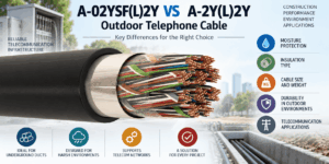
A-02YSF(L)2Y vs A-2Y(L)2Y Outdoor Telephone Cable
A-02YSF(L)2Y vs A-2Y(L)2Y is an important comparison when selecting copper outdoor telephone cable for telecommunications networks, und...

RS-485 Cable vs Instrumentation Cable: Can Instrumentation Cable Be Used for Modbus RTU?
A Modbus RTU cable must do more than carry a low-voltage digital signal from one device to another. Modbus RTU commonly uses an RS-485 ...

Ethernet Cable for PoE: Conductor Size, Heat and Bundle Performance
A PoE Ethernet cable carries data and electrical power over the same balanced twisted-pair cabling system. This capability simplifies t...
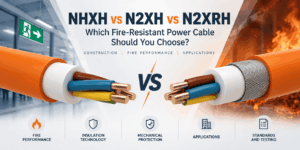
NHXH vs N2XH vs N2XRH: Which Fire-Resistant Power Cable Should You Choose?
NHXH vs N2XH vs N2XRH is an important comparison when specifying 0.6/1 kV power cables for emergency and life-safety systems. Although ...

How to Specify Low Current Cables for Infrastructure Projects
A professional low current cable specification should define much more than a cable name, conductor count or sheath colour. Infrastruct...


