





 President’s Message
Blog
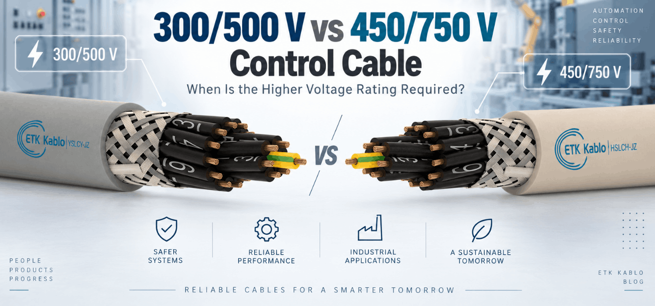
300/500 V vs 450/750 V Control Cable: When Is the Higher Voltage Rating Required?
Reading Time: 15 minutes
Control cable voltage rating is one of the most important electrical parameters to check when selecting cables for industrial machinery, automation systems, control panels and auxiliary circuits. Two of the most common ratings are 300/500 V and 450/750 V, but the difference is often misunderstood.
The higher rating does not automatically mean that the cable carries more current, transmits signals more accurately or provides better electromagnetic compatibility. Instead, 300/500 V and 450/750 V describe the electrical stress that the cable insulation system is designed to withstand during normal operation.
For example, a 300/500 V cable can be entirely appropriate for many 24 VDC, 110 VAC, 230 VAC and conventional 230/400 V control systems. However, applications with higher conductor-to-earth or conductor-to-conductor voltage can require a 450/750 V construction.
Therefore, engineers should select the voltage class from the actual circuit voltage, installation rules and equipment specification rather than automatically choosing the highest available rating.
Quick answer: 300/500 V normally means the cable is rated for 300 V between an insulated conductor and earth and 500 V between conductors. A 450/750 V control cable raises those reference values to 450 V and 750 V. The higher rating becomes necessary when the circuit voltage exceeds the limits of the 300/500 V class, when the applicable standard or equipment specification requires 450/750 V, or when the cable forms part of a system with higher electrical stress. It does not automatically increase current-carrying capacity.
Control Cable Voltage Rating at a Glance
| Characteristic | 300/500 V | 450/750 V |
|---|---|---|
| U₀ | 300 V conductor-to-earth | 450 V conductor-to-earth |
| U | 500 V conductor-to-conductor | 750 V conductor-to-conductor |
| Typical control use | Low-voltage control and automation | Higher-voltage auxiliary and control circuits |
| Suitable for 24 VDC control | Yes | Yes |
| Suitable for 230 VAC control | Generally yes | Yes |
| Suitable for 230/400 V system by voltage rating | Generally yes | Yes |
| Suitable for 400/690 V system by voltage rating | No | Yes |
| Higher current capacity automatically? | No | No |
| Better shielding automatically? | No | No |
| Higher dielectric capability | Standard level | Higher level |
Consequently, the voltage rating should be treated as an insulation-system requirement rather than a general indicator of cable quality.
What Does Control Cable Voltage Rating Mean?
A control cable voltage rating identifies the reference voltage for which the cable insulation system has been designed.
For AC systems, cable ratings commonly appear in the form:
U₀/U
The two values do not represent minimum and maximum voltage.
Instead:
- U₀ represents the rated RMS voltage between an insulated conductor and earth or an earthed metallic part.
- U represents the rated RMS voltage between two conductors in the cable or electrical system.
Therefore, both values matter when deciding whether a cable is suitable for a circuit.
Control Cable Voltage Rating: What Does 300/500 V Mean?
For a 300/500 V control cable:
- U₀ = 300 V
- U = 500 V
This means the insulation system is designed around a nominal conductor-to-earth voltage of 300 V and conductor-to-conductor voltage of 500 V.
As a result, the rating is suitable for many common industrial control systems operating substantially below those values.
Typical examples include:
- 24 VDC PLC circuits
- 24 VDC sensors and actuators
- 48 V control circuits
- 110 VAC control circuits
- 230 VAC auxiliary circuits
- Many 230/400 V machine-control applications
Therefore, 300/500 V should not be considered a “low-quality” cable merely because a 450/750 V alternative exists.
Control Cable Voltage Rating: What Does 450/750 V Mean?
A 450/750 V cable uses a higher control cable voltage rating.
In this case:
- U₀ = 450 V
- U = 750 V
The cable insulation system can therefore accommodate higher nominal electrical stress.
Consequently, 450/750 V becomes relevant when equipment operates above the voltage limits appropriate for a 300/500 V cable or when the project standard specifically requires the higher rating.
Control Cable Voltage Rating: 300/500 V vs 450/750 V
The fundamental difference is dielectric capability.
A 450/750 V cable has an insulation construction designed for a higher electrical operating voltage than a 300/500 V cable.
Depending on the product family, this can involve:
- Different insulation thickness
- Different insulation design
- Higher dielectric test requirements
- Different overall cable dimensions
- Different applicable standards
However, those changes are product-specific.
Therefore, engineers should not assume that every 450/750 V cable is simply a thicker version of the corresponding 300/500 V model.
Control Cable Voltage Rating and a 230/400 V System
A common European low-voltage three-phase system operates at approximately 230 V between phase and neutral and 400 V between phases.
From the voltage-rating perspective alone:
- 230 V conductor-to-earth is below the 300 V U₀ rating.
- 400 V conductor-to-conductor is below the 500 V U rating.
Therefore, a 300/500 V cable can be electrically compatible with a conventional 230/400 V system when the cable construction, application and applicable installation requirements also permit its use.
This point is important because many buyers assume that any cable associated with a 400 V machine must automatically carry a 450/750 V rating.
That assumption is not correct.
Control Cable Voltage Rating for 400/690 V Systems
The situation changes significantly for a 400/690 V three-phase system.
In such a system, the approximate phase-to-earth voltage is 400 V, while the phase-to-phase voltage is 690 V.
A 300/500 V cable would therefore be insufficient because:
- 400 V exceeds the 300 V U₀ rating.
- 690 V exceeds the 500 V U rating.
By contrast, a 450/750 V cable provides:
- 450 V conductor-to-earth capability
- 750 V conductor-to-conductor capability
Therefore, 450/750 V becomes the appropriate minimum voltage class from this electrical-rating perspective.
Control Cable Voltage Rating for 24 VDC Systems
Industrial automation commonly uses 24 VDC for sensors, PLC inputs, relays and actuators.
At this voltage, both 300/500 V and 450/750 V cable ratings provide far more dielectric capability than the circuit requires.
Therefore, choosing 450/750 V solely because the circuit operates at 24 VDC usually provides no electrical necessity.
Other factors should determine the cable:
- Core count
- Conductor size
- Shielding
- Flexibility
- Oil resistance
- Fire performance
- Mechanical environment
Consequently, a correctly designed 300/500 V cable can be a more efficient choice for many low-voltage automation circuits.
Control Cable Voltage Rating for 110 V and 230 V Circuits
110 VAC and 230 VAC control circuits remain common in industrial machinery and building systems.
Both voltage levels are comfortably within a 300/500 V cable rating when the conductor-to-earth and conductor-to-conductor conditions remain within the permitted limits.
Therefore, a higher 450/750 V rating is generally not required merely because the control voltage is 230 VAC.
However, the cable can still require 450/750 V for another reason, such as:
- Machine manufacturer specification
- Project standard
- Mixed-voltage wiring
- Installation regulation
- Higher adjacent circuit voltage
Why the Circuit Voltage Matters More Than the Equipment Nameplate
A machine can have a 400 V or 690 V incoming supply while individual control circuits operate at only 24 VDC.
Therefore, the supply voltage written on the machine nameplate does not automatically determine the required control cable voltage rating for every cable inside the machine.
Engineers should identify the actual voltage carried by each cable.
For example:
- Main motor feeder: 400 V three-phase
- Contactor coil: 230 VAC
- PLC input: 24 VDC
- Encoder signal: low-voltage electronic signal
These circuits can require completely different cable constructions even though they belong to the same machine.
Does 450/750 V Mean Higher Current Capacity?
No.
This is one of the most common misunderstandings surrounding control cable voltage rating.
Voltage rating describes insulation capability.
Current-carrying capacity depends primarily on factors such as:
- Conductor cross-section
- Copper resistance
- Insulation temperature rating
- Ambient temperature
- Installation method
- Grouping
- Number of loaded conductors
Therefore, a 0.75 mm² 450/750 V conductor does not automatically carry more current than a 0.75 mm² 300/500 V conductor.
The applicable datasheet and installation conditions should determine the current rating.
Voltage Rating vs Conductor Cross-Section
Voltage and conductor size solve two different engineering problems.
The voltage rating ensures adequate insulation against electrical stress.
The conductor cross-section controls resistance, voltage drop and current-carrying capability.
For example, a project can require:
- 0.75 mm² / 300/500 V
- 1.5 mm² / 300/500 V
- 0.75 mm² / 450/750 V
- 1.5 mm² / 450/750 V
Therefore, increasing voltage rating should not substitute for selecting the correct conductor size.
Does 450/750 V Mean Better Signal Performance?
No.
A higher control cable voltage rating does not automatically improve signal integrity.
For analog signals, encoder circuits or noise-sensitive control systems, more relevant parameters can include:
- Screening
- Pair twisting
- Capacitance
- Conductor resistance
- EMC installation
Therefore, a 300/500 V screened control cable can provide better noise immunity than an unscreened 450/750 V cable.
Voltage rating and electromagnetic compatibility should be evaluated independently.
Does 450/750 V Mean Better Shielding?
No.
A cable can be:
- 300/500 V unscreened
- 300/500 V screened
- 450/750 V unscreened
- 450/750 V screened
The voltage class describes insulation.
Meanwhile, terms such as CY, braid-screened, foil-screened or individually screened describe electromagnetic protection.
Consequently, engineers should never use voltage rating as a substitute for a shielding specification.
Control Cable Voltage Rating and Insulation Construction
A higher voltage class normally requires the manufacturer to design the insulation system for greater dielectric stress.
Depending on the cable family, this can affect:
- Insulation-wall thickness
- Core diameter
- Overall cable diameter
- Cable weight
- Minimum bending radius
However, exact dimensions vary with product design.
Therefore, procurement teams should compare actual manufacturer tables rather than assume a fixed dimensional increase between 300/500 V and 450/750 V.
Control Cable Voltage Rating and Test Voltage
Rated voltage and test voltage are not the same parameter.
The control cable voltage rating describes the continuous reference operating voltage for which the cable is designed.
A dielectric test voltage is a substantially higher voltage applied for a limited test period to verify insulation integrity.
For example, ETK’s standard 300/500 V YSLY-JZ construction uses a higher short-duration dielectric test than its normal operating voltage.
ETK’s higher-voltage control-cable variants also use an appropriately higher dielectric test requirement.
Therefore, buyers should never interpret a 2,000 V or 2,500 V test voltage as the continuous operating voltage of the cable.
Why Test Voltage Is Higher Than Rated Voltage
The dielectric test verifies that the insulation system can withstand a controlled electrical stress without breakdown.
This provides manufacturing-quality assurance.
However, continuous operation at the test voltage would represent a completely different electrical condition.
Consequently:
Rated voltage = continuous design reference.
Test voltage = temporary dielectric verification.
These numbers should never be compared directly as equivalent cable ratings.
Control Cable Voltage Rating for Industrial Machinery
Industrial machinery can contain both voltage classes.
For low-voltage command circuits, sensors and relays, 300/500 V can provide sufficient electrical performance.
Meanwhile, higher-voltage auxiliary circuits can justify a 450/750 V construction.
Therefore, machine builders should create a cable schedule based on the individual circuit rather than apply one voltage rating to the entire machine.
This approach can optimize:
- Cable diameter
- Panel space
- Flexibility
- Material cost
- Installation effort
Control Cable Voltage Rating in Motor-Control Circuits
Motor-control systems often combine low-voltage signalling with higher-voltage switching circuits.
A PLC output can operate at 24 VDC while another multicore cable carries 230 VAC or 400 VAC auxiliary functions.
Therefore, the required cable voltage class depends on which conductors share the cable and the maximum voltage between those conductors.
In particular, mixed-voltage cables require careful review of:
- Insulation rating
- Circuit segregation
- Equipment rules
- Applicable installation standard
Consequently, the lowest-voltage signal inside a multicore cable does not necessarily determine the cable rating.
Can 300/500 V and 450/750 V Circuits Share the Same Cable?
The answer depends on the complete electrical design and applicable installation rules.
When multiple circuits share a multicore cable, the insulation system generally has to accommodate the highest electrical stress that can occur between conductors.
Moreover, safety and functional-separation rules can restrict which circuit types may share the same cable.
Therefore, designers should not combine different voltage classes simply because enough spare cores are available.
Control Cable Voltage Rating for Control Panels
Inside control panels, circuit voltage can range from extra-low voltage to several hundred volts.
For this reason, the panel designer should identify:
- Control voltage
- Auxiliary voltage
- Maximum conductor-to-earth voltage
- Maximum conductor-to-conductor voltage
- Segregation requirements
Many standard control-panel applications remain comfortably within the 300/500 V range.
Nevertheless, 450/750 V can become necessary where higher-voltage equipment or customer specifications require it.
300/500 V vs 450/750 V for HVAC and BMS
Building-management and HVAC systems frequently operate at several voltage levels.
Examples include:
- 24 VAC actuators
- 24 VDC sensors
- 230 VAC valves
- 230 VAC contactors
- Low-voltage BMS communication circuits
Therefore, a 300/500 V control cable can satisfy many conventional BMS and HVAC applications.
However, higher-voltage circuits or project requirements can justify 450/750 V.
Again, the correct choice comes from the circuit design rather than the words “BMS cable” or “HVAC cable.”
When 450/750 V Provides Useful Design Margin
Sometimes engineers choose a higher control cable voltage rating even when the nominal circuit voltage does not strictly require it.
Possible reasons include:
- Customer standardization
- Machine-platform standardization
- Future system modification
- Higher dielectric specification
- OEM requirements
- Export-market requirements
However, additional voltage margin should provide a real engineering or commercial benefit.
Otherwise, the result can be unnecessary over-specification.
Why Over-Specifying 450/750 V Can Be Unnecessary
A higher cable rating can increase manufacturing requirements and, depending on construction, cable diameter or cost.
It can also reduce flexibility if additional insulation material is required.
Therefore, automatically specifying 450/750 V for a 24 VDC control circuit may offer little practical benefit.
A technically optimized specification should achieve the required safety margin without adding unnecessary material.
Why Under-Specifying Voltage Is More Serious
Using a cable below the required voltage class creates a fundamentally different risk.
The insulation system may experience electrical stress beyond its intended design condition.
As a result, long-term insulation reliability can deteriorate.
Therefore, the cable voltage rating should never fall below the requirements of the circuit and applicable standard.
Control Cable Voltage Rating and IEC 60227
IEC 60227 is an important international family covering PVC-insulated cables with rated voltages up to and including 450/750 V.
The current general requirements are contained in IEC 60227-1:2024.
However, an important distinction exists for control cable engineers.
IEC 60227-7:2024 specifically covers screened and unscreened flexible control cables with two or more conductors at rated voltages up to and including 300/500 V.
Therefore, engineers should not automatically claim that a 450/750 V proprietary control-cable construction complies with IEC 60227-7 simply because the broader IEC 60227 family extends to 450/750 V.
The exact applicable product standard must be checked.
Control Cable Voltage Rating and EN 50565-1
EN 50565-1 provides guidance for selecting and using cables with rated voltages up to 450/750 V.
The standard reinforces an important selection principle: cable rated voltage must be at least equal to the nominal system voltage in terms of both conductor-to-earth and conductor-to-conductor stress.
Therefore, engineers should evaluate both U₀ and U rather than compare only one number.
Maximum Operating Voltage vs Rated Voltage
The rated voltage printed on the cable is a reference class rather than the absolute voltage at which insulation instantly fails.
Relevant standards can define limited maximum continuous operating voltages above the nominal rating.
For example, guidance for these voltage classes allows some tolerance above nominal system voltage.
However, designers should not use that tolerance as a routine method for selecting an underspecified cable.
Therefore, the normal design approach is still to select a cable whose U₀/U rating meets or exceeds the nominal system requirement.
300/500 V vs 450/750 V for DC Systems
DC applications require additional care because the familiar U₀/U designations are most commonly presented in relation to AC system voltage.
Some cable standards provide permissible DC values derived from the AC voltage class.
However, the allowable DC application should come from the relevant cable standard and manufacturer documentation.
Therefore, engineers should not simply assume that “300/500 V” means a universal 500 VDC operating limit in every installation.
What Happens Above 450/750 V?
If the circuit requirements exceed the 450/750 V class, the next solution is not simply to keep using the same control cable.
The project may require a higher-rated cable family.
For example, ETK’s control-cable portfolio also includes 0.6/1 kV flexible constructions.
A 0.6/1 kV rating provides:
- 600 V conductor-to-earth reference voltage
- 1000 V conductor-to-conductor reference voltage
Therefore, projects approaching or exceeding the limits of 450/750 V should evaluate a purpose-designed 0.6/1 kV cable rather than stretch the lower voltage class beyond its intended application.
450/750 V vs 0.6/1 kV Control Cable
The same selection logic continues at the next voltage level.
450/750 V does not automatically replace 0.6/1 kV simply because both are classified as low-voltage cables.
A circuit whose conductor-to-earth or conductor-to-conductor voltage exceeds the 450/750 V class requires the higher insulation rating.
Therefore, the hierarchy should follow actual system voltage:
- 300/500 V where sufficient
- 450/750 V where required
- 0.6/1 kV where the circuit exceeds the lower classes or the specification demands it
Control Cable Voltage Rating and Cable Flexibility
A higher voltage rating does not automatically mean a cable is less flexible.
Flexibility depends largely on:
- Conductor class
- Strand diameter
- Insulation material
- Sheath material
- Overall construction
- Cable diameter
Many 300/500 V and 450/750 V ETK control-cable variants use Class 5 stranded copper conductors.
Therefore, engineers should compare the manufacturer’s actual bending radius and construction rather than infer flexibility from voltage rating alone.
Control Cable Voltage Rating and JZ/OZ Identification
JZ and OZ describe core-identification configuration, not voltage class.
A JZ cable includes black numbered working cores together with a green-yellow protective conductor.
An OZ cable uses numbered working cores without the green-yellow conductor.
Therefore, a cable can theoretically combine JZ or OZ identification with different voltage ratings according to the product family.
The JZ/OZ designation should not be used to determine whether a cable is 300/500 V or 450/750 V.
Control Cable Voltage Rating and Screening
Screening also remains independent of voltage class.
For example, a project can require:
- Unscreened 300/500 V
- Screened 300/500 V
- Unscreened 450/750 V
- Screened 450/750 V
Therefore, voltage rating should address electrical insulation while shielding addresses electromagnetic compatibility.
Control Cable Voltage Rating and PVC vs LSZH
Material system and voltage rating are separate specifications as well.
A control cable can use PVC materials or halogen-free compounds while being designed for a particular voltage class.
Consequently, public buildings, infrastructure and enclosed environments can require halogen-free construction without automatically changing the electrical voltage requirement.
Likewise, upgrading from 300/500 V to 450/750 V does not automatically make a cable LSZH.
Common Control Cable Voltage Rating Mistakes
Assuming 450/750 V Is Always Better
The higher rating provides greater dielectric capability, but unnecessary over-specification can add cost and complexity without improving the circuit.
Assuming 300/500 V Cannot Be Used on a 400 V System
A conventional 230/400 V system can fall within the U₀/U values of a 300/500 V cable, subject to the applicable product and installation requirements.
Using 300/500 V on a 400/690 V System
That system exceeds both the 300 V conductor-to-earth value and the 500 V conductor-to-conductor value.
Confusing Voltage Rating With Current Capacity
Current capacity depends primarily on conductor size and installation conditions.
Confusing Voltage Rating With Test Voltage
Short-duration dielectric test voltage is much higher than the continuous rated voltage.
Assuming Higher Voltage Means Better Shielding
EMC screening is independent of insulation voltage class.
Ignoring U₀
Checking only phase-to-phase voltage can miss an excessive conductor-to-earth voltage.
Ignoring U
Checking only conductor-to-earth voltage can miss excessive voltage between conductors.
Using Machine Supply Voltage for Every Internal Cable
Individual circuits can operate at very different voltage levels inside the same machine.
Ignoring Mixed-Voltage Cores
The highest electrical stress between conductors can control the required cable insulation rating.
Assuming IEC 60227-7 Covers 450/750 V Control Cable
IEC 60227-7:2024 specifically addresses control cables up to and including 300/500 V.
Ignoring Manufacturer Data
Two cables with the same voltage rating can still have different temperature, flexibility, fire and mechanical properties.
How to Select the Correct Control Cable Voltage Rating
Identify the Actual Circuit Voltage
Start with the voltage that will actually appear on the conductors rather than the general machine supply rating.
Check Conductor-to-Earth Voltage
Compare the maximum nominal value with U₀.
Check Conductor-to-Conductor Voltage
Next, compare the maximum nominal voltage between cores with U.
Review Mixed-Voltage Circuits
Where different circuits share one cable, evaluate the maximum possible electrical stress between conductors.
Check the Applicable Product Standard
Ensure that the requested voltage class matches the scope of the claimed cable standard.
Review Equipment Requirements
Machine builders and OEMs can specify a higher minimum cable rating than the circuit voltage alone would require.
Confirm Conductor Size Separately
Select cross-section according to current, voltage drop and mechanical requirements.
Define Shielding Separately
Add the appropriate braid or foil system where electromagnetic compatibility requires it.
Select the Material System
Choose PVC, LSZH or another required material according to fire and environmental conditions.
Move to 0.6/1 kV When Necessary
If 450/750 V does not provide sufficient U₀/U capability, choose a cable family specifically designed for the higher voltage class.
Verify the Manufacturer Datasheet
Finally, confirm voltage rating, test voltage, conductor size, temperature range, bending radius and construction for the exact product.
Control Cable Voltage Rating RFQ Checklist
A professional control cable voltage rating specification should define the circuit rather than simply requesting “high-voltage control cable.”
Useful RFQ information includes:
- Required U₀/U rating
- 300/500 V, 450/750 V or 0.6/1 kV
- Nominal system voltage
- Maximum conductor-to-earth voltage
- Maximum conductor-to-conductor voltage
- AC or DC system
- Number of cores
- JZ or OZ identification
- Conductor cross-section
- Conductor class
- Screened or unscreened construction
- Foil or braid screen where required
- PVC or LSZH materials
- Operating temperature
- Current requirement
- Minimum bending radius
- Fixed or flexible installation
- Flame-retardant requirement
- CPR class where applicable
- Oil or chemical resistance where required
- Applicable product standard
- Required dielectric test
- Required technical documentation
Consequently, manufacturers can select the correct insulation design without guessing from the phrase “control cable.”
ETK Kablo Control Cable Voltage Rating Options
ETK Kablo manufactures control cables across several voltage classes for industrial automation, machinery, control panels and infrastructure projects.
The standard ETK control-cable portfolio includes 300/500 V constructions such as:
For applications requiring the higher control cable voltage rating, ETK also offers 0.45/0.75 kV variants within several major families, including YSLY-JZ, HSLH-JZ, YSLCY-JZ and HSLCH-JZ constructions.
Moreover, ETK’s portfolio extends to 0.6/1 kV flexible control cables for projects requiring still greater dielectric capability.
Therefore, ETK can match voltage rating with shielding, PVC or halogen-free materials, conductor size and application requirements rather than treating every industrial control circuit as the same cable specification.
Frequently Asked Questions About Control Cable Voltage Rating
What does 300/500 V mean on a control cable?
It means the cable has a rated voltage of 300 V between an insulated conductor and earth and 500 V between conductors.
What does 450/750 V mean?
It means the cable is rated for 450 V conductor-to-earth and 750 V conductor-to-conductor.
What does U₀/U mean?
U₀ refers to conductor-to-earth rated voltage, while U refers to conductor-to-conductor rated voltage.
Is 450/750 V better than 300/500 V?
It provides higher dielectric capability, but it is not automatically better for a lower-voltage circuit.
Can 300/500 V control cable be used on 24 VDC?
Yes, the voltage class provides far more dielectric capability than a conventional 24 VDC control circuit requires.
Can 300/500 V cable be used for 230 VAC?
Generally yes from the voltage-rating perspective, provided the cable construction and applicable installation rules permit the application.
Can 300/500 V cable be used on a 400 V three-phase system?
In a conventional 230/400 V system, both conductor-to-earth and conductor-to-conductor nominal voltages can fall within a 300/500 V cable rating.
Can 300/500 V cable be used on a 690 V system?
A 400/690 V system exceeds the 300/500 V U₀/U rating, so a higher voltage class is required.
Is 450/750 V suitable for 400/690 V systems?
Yes from the nominal voltage-rating perspective because approximately 400 V conductor-to-earth and 690 V conductor-to-conductor remain below 450/750 V.
Does 450/750 V carry more current?
Not automatically. Current capability depends mainly on conductor size, temperature and installation conditions.
Does 450/750 V have thicker insulation?
A higher voltage class generally requires an insulation design suitable for greater electrical stress, although exact thickness depends on the cable construction.
Does a higher voltage rating improve EMI protection?
No. Shielding and voltage rating are separate cable characteristics.
Is test voltage the same as operating voltage?
No. Test voltage is temporarily applied to verify dielectric integrity, while rated voltage describes normal operating capability.
Can screened cable be 300/500 V?
Yes. Both screened and unscreened control cables can use a 300/500 V rating.
Can screened cable be 450/750 V?
Yes. Shielding does not prevent a control cable from being designed for 450/750 V.
Does JZ mean 300/500 V?
No. JZ identifies the core arrangement and presence of a green-yellow protective conductor, not the voltage class.
Does OZ mean 450/750 V?
No. OZ also describes core identification and does not determine rated voltage.
When should 450/750 V be specified?
Specify it when the circuit voltage, equipment standard or project requirement exceeds what the 300/500 V class can support or explicitly requires the higher voltage class.
When should 0.6/1 kV control cable be used?
Use the higher class when the system exceeds 450/750 V capability or when the equipment and project specification require a 0.6/1 kV cable.
How should control cable voltage rating be selected?
Compare the circuit’s conductor-to-earth and conductor-to-conductor voltages with U₀/U, then confirm the applicable standard, manufacturer datasheet and installation requirements.
Conclusion
Control cable voltage rating should match the actual electrical stress of the circuit rather than serve as a general measure of cable quality.
A 300/500 V cable is suitable for many industrial automation and machinery circuits, including common 24 VDC, 110 VAC, 230 VAC and conventional 230/400 V applications when the complete installation requirements permit it.
Meanwhile, 450/750 V provides greater dielectric capability and becomes necessary when conductor-to-earth or conductor-to-conductor voltage exceeds the lower class. A 400/690 V system is a clear example where the 450/750 V class becomes relevant.
However, higher voltage rating does not automatically provide more current capacity, stronger shielding or better signal transmission.
Those characteristics must be specified separately.
Select U₀/U Before Choosing the Cable Family
First, identify the true operating voltage of the circuit.
Next, compare conductor-to-earth voltage with U₀ and conductor-to-conductor voltage with U.
Afterward, select conductor size, shielding, core identification and material system according to the application.
Finally, verify the product standard and manufacturer’s technical data for the exact cable.
Ultimately, the correct choice between 300/500 V and 450/750 V is not “lower quality versus higher quality.” It is a question of matching the insulation system to the electrical conditions of the control circuit without either under-specifying or unnecessarily over-specifying the cable.
Benzer yazılar
0.5 vs 0.75 vs 1.0 vs 1.5 mm² Control Cable: How to Select Conductor Size
Control cable conductor size affects resistance, voltage drop, current-carrying capability, cable diameter, flexibility and cost. Among...
300/500 V vs 450/750 V Control Cable: When Is the Higher Voltage Rating Required?
Control cable voltage rating is one of the most important electrical parameters to check when selecting cables for industrial machinery...

Outdoor Ethernet Cable: PE, UV Resistance, Aerial and Duct Applications
Outdoor Ethernet cable applications require more than standard Cat 6 or Cat 6A transmission performance. A cable installed outside a bu...
Railway Data Cables: Ethernet, RS-485, CAN Bus, MVB and WTB Explained
Railway data cables form the communication infrastructure that connects electronic equipment across modern trains. Train control system...
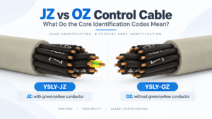
JZ vs OZ Control Cable: What Do the Core Identification Codes Mean?
JZ vs OZ control cable is a common comparison when specifying flexible multicore cables for industrial machinery, control panels, autom...
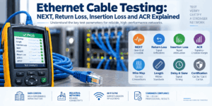
Ethernet Cable Testing: NEXT, Return Loss, Insertion Loss and ACR Explained
Ethernet cable testing verifies whether a twisted-pair copper cabling system can transmit data within the electrical performance limits...

Fiber Optic Cable Attenuation: 850, 1310, 1550 and 1625 nm Explained
Fiber optic cable attenuation describes the reduction in optical power as light travels through an optical fiber. It is normally expres...
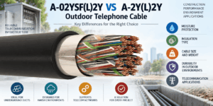
A-02YSF(L)2Y vs A-2Y(L)2Y Outdoor Telephone Cable
A-02YSF(L)2Y vs A-2Y(L)2Y is an important comparison when selecting copper outdoor telephone cable for telecommunications networks, und...
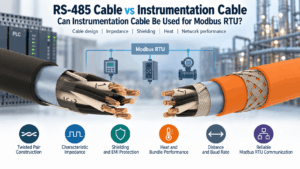
RS-485 Cable vs Instrumentation Cable: Can Instrumentation Cable Be Used for Modbus RTU?
A Modbus RTU cable must do more than carry a low-voltage digital signal from one device to another. Modbus RTU commonly uses an RS-485 ...

Ethernet Cable for PoE: Conductor Size, Heat and Bundle Performance
A PoE Ethernet cable carries data and electrical power over the same balanced twisted-pair cabling system. This capability simplifies t...
NHXH vs N2XH vs N2XRH: Which Fire-Resistant Power Cable Should You Choose?
NHXH vs N2XH vs N2XRH is an important comparison when specifying 0.6/1 kV power cables for emergency and life-safety systems. Although ...

How to Specify Low Current Cables for Infrastructure Projects
A professional low current cable specification should define much more than a cable name, conductor count or sheath colour. Infrastruct...


