





 President’s Message
Blog
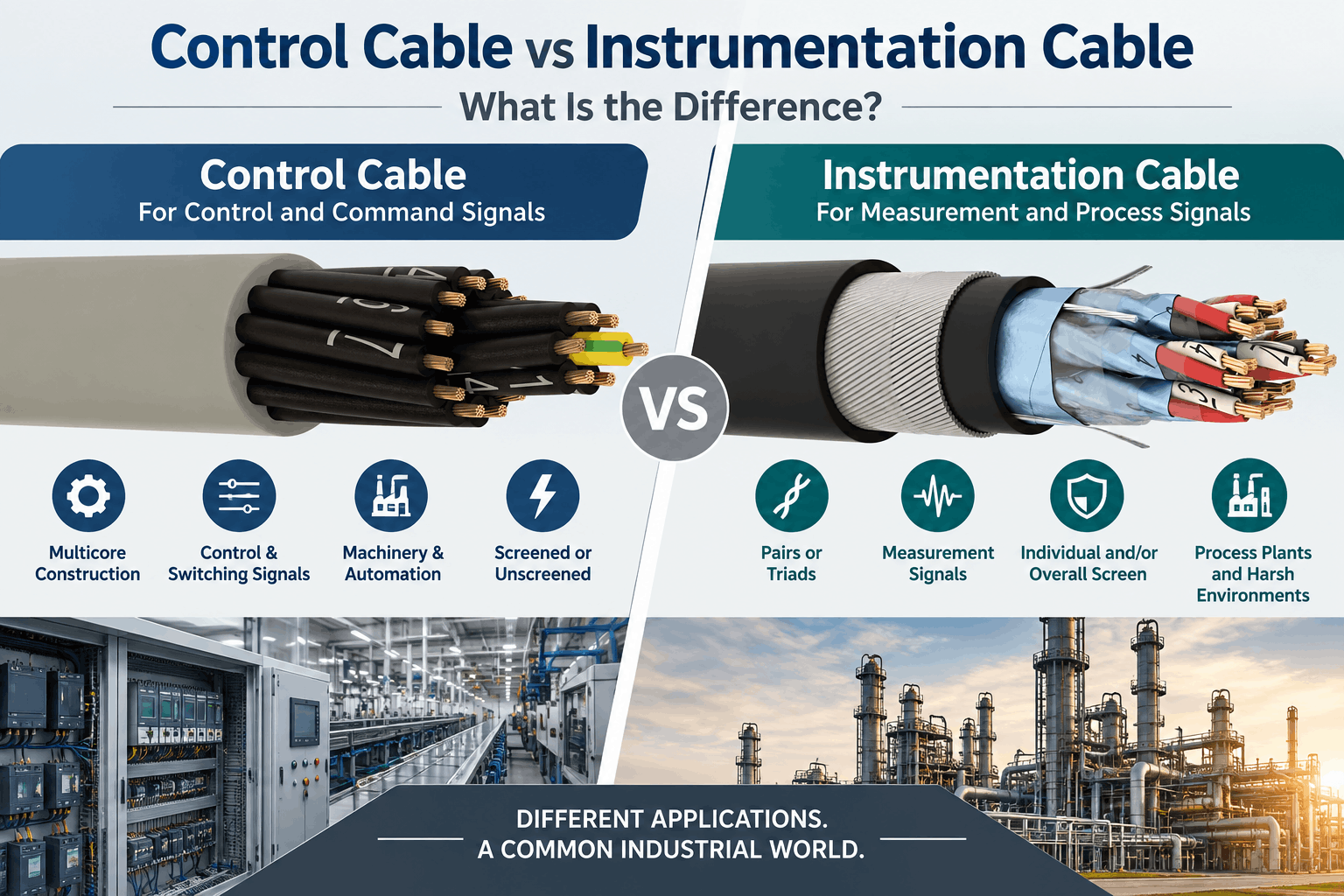
Control Cable vs Instrumentation Cable: What Is the Difference?
Reading Time: 16 minutes
Control vs instrumentation cable selection is an important engineering decision in industrial automation, manufacturing, oil and gas, petrochemical, energy and infrastructure projects. Although both cable families can transmit signals between equipment, they are designed around different electrical, construction and application priorities.
Control cables are commonly used to transmit commands, switching signals and control functions between panels, relays, contactors, actuators, motors and automation equipment. Instrumentation cables, meanwhile, are typically designed for low-level analogue or digital measurement signals between field instruments and monitoring or process-control systems.
However, the distinction is not absolute. Industrial standards and project specifications sometimes use the terms instrumentation and control together because both cable families can operate within automation systems. Therefore, cable selection should be based on the signal type, conductor arrangement, screening requirement, electrical characteristics, installation environment and applicable project standard rather than the product name alone.
Quick answer: A control cable normally carries control commands between automation equipment and frequently uses multicore construction. An instrumentation cable typically carries measurement and process signals and commonly uses twisted pairs or triads with individual and/or overall screening. Instrumentation cables generally place greater emphasis on signal integrity, electromagnetic interference control and defined electrical transmission characteristics.
Control vs Instrumentation Cable at a Glance
| Characteristic | Control Cable | Instrumentation Cable |
|---|---|---|
| Primary purpose | Control and command functions | Measurement and process signal transmission |
| Typical conductor arrangement | Multicore | Pairs or triads |
| Typical signals | On/off, switching, control, auxiliary circuits | Analogue and digital instrumentation signals |
| Screening | Optional depending on application | Frequently required |
| Individual pair/triad screen | Uncommon in general control cable | Common option |
| Overall screen | Available | Common |
| EMI protection priority | Application dependent | Often high |
| Capacitance control | Usually less critical | Often more important |
| Typical environments | Machinery, panels, factories, automation | Process plants, oil and gas, petrochemical, industrial measurement |
| Armouring | Available | Available |
| LSZH construction | Available | Available |
| Typical ETK families | YSLY, YSLCY, YSLYCY, HSLH, HSLCH, HSLHCH | RE-2X(St)Y, RE-2X(St)H and armored derivatives |
These differences represent common design practices rather than an absolute rule. Consequently, the technical datasheet and project specification always take priority over the generic cable-family name.
What Is a Control Cable?
A control cable connects electrical and automation equipment that must exchange commands or control functions.
Typical applications include connections between:
- Control panels
- Programmable logic controllers
- Relays
- Contactors
- Limit switches
- Actuators
- Solenoid valves
- Auxiliary equipment
- Machine control systems
In many applications, the cable contains multiple individually insulated conductors assembled together under a common outer sheath.
For example, a machine might require numerous conductors for start, stop, status, interlock and auxiliary functions. A multicore control cable can carry these connections within one cable.
Therefore, conductor count, voltage rating, flexibility, screening and mechanical protection are common control-cable selection parameters.
What Is an Instrumentation Cable?
An instrumentation cable is primarily designed to transmit measurement, monitoring and process-control signals between field instruments and control or monitoring equipment.
Typical field devices include:
- Pressure transmitters
- Flow transmitters
- Level transmitters
- Temperature instrumentation
- Process sensors
- Analyzers
- Control valves
- Distributed control system I/O
- Remote I/O systems
Instrumentation circuits frequently carry relatively low-level signals. Therefore, electromagnetic interference can become more significant than it would be for a simple switching circuit.
For this reason, instrumentation cables often use twisted pairs or triads together with metallic screening.
Depending on the application, each pair or triad can have its own screen, while the complete cable can also include an overall screen.
Control vs Instrumentation Cable: The Fundamental Difference
The easiest way to understand the distinction is to consider the function of the signal.
A control cable commonly answers the question:
What should the equipment do?
An instrumentation cable commonly answers:
What is happening in the process?
For example, a pressure transmitter might send a measurement signal toward a distributed control system through an instrumentation cable.
The control system can then evaluate that measurement and issue a command to another piece of equipment.
Consequently, instrumentation and control cables can operate within the same automation loop while performing different roles.
Control vs Instrumentation Cable Construction
Construction is one of the clearest practical differences between the two cable families.
A conventional control cable often contains:
- Copper conductors
- Individual conductor insulation
- Multicore assembly
- Optional overall screen
- Optional inner sheath
- Optional armour
- Outer sheath
An instrumentation cable frequently contains:
- Copper conductors
- Pair or triad insulation
- Twisted pairs or triads
- Optional individual pair or triad screens
- Optional overall screen
- Optional bedding or inner sheath
- Optional armour
- Outer sheath
Accordingly, instrumentation cables can require more complex manufacturing processes because pair geometry and screening configuration affect signal performance.
Multicore vs Pair and Triad Construction
General control cables are commonly organized as multicore cables.
For instance, a 12-core control cable contains twelve individually insulated conductors assembled into one cable.
Instrumentation cables, by contrast, are commonly specified by the number of pairs or triads.
A pair contains two associated conductors, while a triad contains three associated conductors.
Examples can include:
- 1 pair
- 2 pairs
- 4 pairs
- 8 pairs
- 12 pairs
- 1 triad
- 4 triads
- 8 triads
Twisting the conductors together helps control electromagnetic interaction and transmission characteristics.
Therefore, cable element construction is an important clue when distinguishing instrumentation cable from a conventional multicore control cable.
Instrumentation Cable Pair vs Triad
Pairs and triads are selected according to the instrument circuit and project specification.
Two-conductor circuits commonly use pairs. Meanwhile, applications requiring three related conductors can use triads.
However, the designer should not select pair or triad construction merely because one appears technically superior.
The correct arrangement depends on the connected equipment, signal circuit and engineering specification.
Therefore, the cable should match the instrumentation architecture rather than forcing the architecture to match the cable.
Why Screening Is Important in Instrumentation Cable
Industrial plants contain many potential sources of electromagnetic interference.
These can include:
- Power cables
- Motors
- Transformers
- Variable-frequency drives
- Switchgear
- Contactors
- Generators
- Industrial machinery
Low-level measurement signals can be more sensitive to this electrical noise.
Therefore, instrumentation cables frequently incorporate aluminium/polyester foil screens, copper drain wires or other screening systems.
Screening helps reduce unwanted electromagnetic coupling between external sources and the signal conductors.
Moreover, individual pair or triad screens can help reduce interaction between different circuits within the same cable.
Individual Screen vs Overall Screen
An overall screen surrounds the combined cable element assembly.
Its primary role is to provide common electromagnetic protection for the cable.
An individual screen, by contrast, surrounds a particular pair or triad.
Therefore, individually screened instrumentation cables can provide additional separation between signal circuits.
Some constructions combine both approaches:
Individual screens + overall screen.
This arrangement can be valuable in process plants containing many instrumentation loops within the same cable.
However, additional screening increases cable diameter, complexity and cost. Consequently, the screen configuration should follow the actual EMC requirement.
PiMF vs TiMF Instrumentation Cable
PiMF generally refers to Pair in Metal Foil construction.
In this arrangement, individual conductor pairs receive their own metallic foil screen.
TiMF, meanwhile, refers to Triad in Metal Foil construction.
Each triad receives its own metallic foil screen.
Therefore, the principal difference is not simply the screen itself. The underlying circuit element is also different: pair versus triad.
This distinction is particularly relevant when engineers prepare instrumentation-cable schedules for complex process-control projects.
Do Control Cables Need Screening?
Not every control cable requires a screen.
Simple switching circuits installed in relatively low-interference environments can use unscreened constructions when permitted by the equipment manufacturer and project design.
However, control cables operating near significant electrical noise sources may benefit from an overall screen.
For example, screened control cables are frequently used around industrial automation systems, electronic control equipment and machinery.
Therefore, screened vs unscreened control cable selection depends on EMC conditions rather than the word “control” alone.
Does Screening Turn a Control Cable Into an Instrumentation Cable?
No.
A screened control cable remains a control cable when its construction and intended application are designed around control circuits.
Likewise, the presence of foil screening does not automatically make a cable suitable for sensitive instrumentation signals.
Other characteristics can matter, including:
- Pair geometry
- Twisting
- Capacitance
- Conductor resistance
- Screen arrangement
- Signal transmission characteristics
Consequently, cable identification should never rely on the visible presence of a metallic screen alone.
Electrical Characteristics of Control vs Instrumentation Cable
Electrical performance requirements differ because the signal functions differ.
For a general control cable, important parameters can include:
- Rated voltage
- Conductor resistance
- Insulation resistance
- Voltage withstand
- Current-carrying requirement
Instrumentation cables can require additional attention to:
- Mutual capacitance
- Capacitance unbalance
- Screen characteristics
- Pair geometry
- Signal attenuation where relevant
- Electrical transmission consistency
Therefore, replacing instrumentation cable with a generic multicore cable merely because conductor size matches can be a serious specification mistake.
Why Capacitance Matters
Every cable has capacitance between its conductors and between conductors and screens.
For many simple control circuits, this is not the dominant cable-selection factor.
However, instrumentation circuits can be more sensitive to capacitance, particularly over longer distances or with specific connected equipment.
Higher capacitance can influence signal behaviour and the permissible cable length in certain circuits.
Consequently, instrumentation-cable datasheets frequently specify electrical parameters that may receive less attention on general-purpose control cables.
Analogue Signals and Instrumentation Cable
Instrumentation cables are widely associated with analogue process signals.
A familiar example is a 4–20 mA instrumentation loop.
The transmitter converts a measured process variable into an electrical signal. The instrumentation cable then carries that signal toward the PLC, DCS or other monitoring equipment.
Because the information carried by the cable represents a measured process value, signal reliability is important.
Therefore, appropriate conductor construction, screening and circuit separation can be critical in electrically noisy industrial environments.
Digital Signals and Instrumentation Cable
Instrumentation cable is not limited to analogue signals.
Modern process plants also use digital communication and digitally superimposed instrumentation protocols.
However, not every generic instrumentation cable is suitable for every industrial communication protocol.
High-speed buses and industrial Ethernet systems can require defined characteristic impedance, attenuation, bandwidth and construction geometry.
Consequently, an ordinary screened instrumentation cable should not automatically be substituted for a dedicated bus or Ethernet cable.
Control Cable for PLC Systems
Programmable logic controllers can interface with numerous field devices.
Control cables can connect PLC systems with:
- Relays
- Contactors
- Switches
- Actuators
- Valves
- Interlocks
- Machine devices
Depending on the circuit, these connections can involve discrete inputs and outputs or other control functions.
Meanwhile, measurement transmitters connected to analogue input modules may instead use instrumentation cable.
Therefore, one PLC cabinet can contain both control and instrumentation cable terminations.
Control Cable for Industrial Machinery
Industrial machinery frequently contains many command and auxiliary circuits.
Applications can include:
- Machine tools
- Conveyors
- Packaging equipment
- Production lines
- Material-handling systems
- Industrial pumps
- Automated assembly systems
Multicore control cables can consolidate numerous connections into one cable construction.
In addition, screened versions can improve EMC performance where sensitive electronic controls are present.
However, flexibility requirements should also be considered. A flexible conductor does not automatically mean that a cable is designed for continuous drag-chain or robotic movement.
Instrumentation Cable for Process Plants
Process industries are among the most important applications for instrumentation cable.
Typical sectors include:
- Oil and gas
- Petrochemical
- Chemical processing
- Refineries
- Power generation
- Water treatment
- Mining
- Industrial manufacturing
These plants can contain thousands of field instruments distributed over large areas.
Consequently, instrumentation cables can be required in large multicircuit pair and triad configurations together with screening, armouring and environmental protection.
Instrumentation Cable for Petrochemical Plants
Petrochemical plants combine complex process measurement with significant electromagnetic and mechanical challenges.
Cables can be routed near motors, pumps, switchgear and power circuits while also being exposed to outdoor weather, hydrocarbons and industrial environments.
Therefore, an instrumentation cable specification can consider:
- Pair or triad construction
- Individual screening
- Overall screening
- Armour
- UV resistance
- Hydrocarbon resistance where specified
- LSZH performance
- Fire performance
As a result, instrumentation cable for petrochemical plants should be selected as an engineered construction rather than simply by conductor size.
Control vs Instrumentation Cable in Oil and Gas Projects
Oil and gas projects commonly require both cable families.
Control cable can serve:
- Motor control circuits
- Valve commands
- Relay circuits
- Interlocks
- Auxiliary systems
Instrumentation cable can serve:
- Pressure measurement
- Flow measurement
- Level measurement
- Temperature monitoring
- Process transmitters
- DCS instrumentation loops
Consequently, project cable schedules should separate these functional requirements even when both cable families share similar sheath, armour or fire-performance requirements.
Control vs Instrumentation Cable Standards
There is no single global standard that defines every cable marketed as a control cable or instrumentation cable.
Applicable requirements depend on the cable construction, voltage, application, region and project specification.
Nevertheless, EN 50288-7 is particularly relevant to instrumentation and control cables used for analogue and digital signal transmission in industrial applications.
The standard addresses multi-element metallic cables intended to connect instruments and control systems.
Therefore, EN 50288-7 also demonstrates an important point: instrumentation and control terminology can overlap at the standards level.
The engineering distinction should consequently be based on construction and electrical performance rather than assuming two completely isolated cable worlds.
EN 50288-7 Instrumentation Cables
EN 50288-7 instrumentation cables can be designed for analogue and digital signal transmission in industrial processes.
Depending on the required construction, cables can be:
- Unscreened
- Overall screened
- Individually screened
- Individually and overall screened
- Armored
- Unarmored
- Designed with environmental protection layers
Accordingly, the standard is highly relevant when instrumentation cable needs defined electrical, mechanical and transmission performance.
Typical Control Cable Constructions
Control cables can use several construction families depending on application.
Examples within the ETK portfolio include:
- YSLY
- YSLCY
- YSLYCY
- HSLH
- HSLCH
- HSLHCH
These names represent different combinations of insulation, sheath and screening construction.
For example, screened variants can be selected when electromagnetic compatibility is more demanding, while halogen-free constructions can be selected for applications requiring low-smoke and halogen-free materials.
YSLY vs YSLCY vs YSLYCY Control Cables
YSLY, YSLCY and YSLYCY belong to the control-cable family but differ in screening and construction.
A project engineer therefore should not specify only “YSL cable.”
Instead, the required electromagnetic environment, installation conditions and equipment interfaces should determine whether an unscreened or screened construction is appropriate.
Consequently, the YSLY vs YSLCY vs YSLYCY control cables comparison is primarily a control-cable construction decision rather than an instrumentation-cable decision.
HSLH vs HSLCH vs HSLHCH Control Cables
Halogen-free control cables can be preferred where smoke and corrosive combustion products are important project considerations.
Within this group, screening requirements can again create different constructions.
Therefore, the HSLH vs HSLCH vs HSLHCH control cable comparison should consider EMC performance together with fire and material requirements.
However, halogen-free construction does not automatically provide circuit integrity or a particular CPR classification.
Typical Instrumentation Cable Constructions
Instrumentation cable families frequently use designations based on polyethylene insulation, screening, armouring and sheath material.
Examples can include:
- RE-2X(St)Y
- RE-2X(St)H
- RE-2X(St)YSWAY
- RE-2X(St)HSWAH
The exact construction should always be confirmed from the cable datasheet because naming conventions can vary according to specification and manufacturer.
Nevertheless, these cable families illustrate how instrumentation products can combine signal-oriented pair or triad design with mechanical and environmental protection.
Control vs Instrumentation Cable Armouring
Both control and instrumentation cables can require mechanical protection.
Steel wire armour can be used where cables face significant mechanical risk or where the project specification requires armored construction.
Steel wire braid can provide another form of mechanical reinforcement in suitable applications.
However, armouring does not determine whether the cable is a control or instrumentation cable.
For example, both an SWA instrumentation cable and an armored control cable can exist.
Therefore, mechanical protection should be considered independently from signal function.
SWA vs SWB for Industrial Cables
SWA and SWB use different metallic protection structures.
Steel wire armour generally provides robust mechanical protection through a layer of steel wires.
Steel wire braid uses braided steel wires and can provide a different balance of flexibility, mechanical performance and cable diameter.
Consequently, neither SWA nor SWB is universally superior.
The correct construction depends on installation conditions, required mechanical protection and project specification.
PVC vs LSZH Control and Instrumentation Cable
Both control and instrumentation cables can use PVC or halogen-free sheath systems.
PVC is widely used in industrial cable constructions because it provides practical mechanical and installation properties.
LSZH materials, meanwhile, are selected where reduced smoke and halogen emissions are required during fire.
Typical applications can include:
- Public infrastructure
- Tunnels
- Transport facilities
- Commercial buildings
- Industrial projects with specific fire requirements
However, LSZH vs PVC cable selection does not determine whether the cable is a control or instrumentation product.
Fire Performance of Control and Instrumentation Cables
Fire performance should be specified separately from cable function.
Depending on the project, control or instrumentation cable can require:
- Flame-retardant performance
- LSZH materials
- CPR reaction-to-fire classification
- Circuit integrity
These requirements address different aspects of cable behaviour.
For example, a halogen-free control cable does not automatically provide circuit integrity. Likewise, an instrumentation cable does not become fire resistant merely because its sheath is LSZH.
Therefore, engineers should define fire performance through the relevant tests and classifications.
Can Control Cable Replace Instrumentation Cable?
Sometimes a particular control cable may be technically suitable for a signal circuit, but substitution should never be assumed.
The engineer must verify characteristics such as:
- Conductor arrangement
- Screening
- Capacitance
- Resistance
- Signal requirements
- Voltage rating
- Environmental performance
- Applicable standard
Therefore, using a generic multicore control cable in place of a specified instrumentation cable simply because conductor size and voltage appear similar can introduce signal-integrity problems.
Can Instrumentation Cable Replace Control Cable?
The opposite substitution also requires engineering review.
An instrumentation cable may have excellent screening and transmission characteristics. However, it might not match the required conductor size, voltage rating, mechanical design or control-circuit requirements.
Moreover, individually screened pairs can add unnecessary cost and cable diameter for a simple control application.
Consequently, using instrumentation cable everywhere is not automatically a superior design strategy.
Control vs Instrumentation Cable for 4–20 mA Signals
4–20 mA process loops are strongly associated with instrumentation systems.
Therefore, twisted and appropriately screened instrumentation cable is commonly specified for these circuits.
Nevertheless, the final cable requirement depends on the instrument manufacturer, loop design, cable length, environmental conditions and project standard.
The important point is that the cable should preserve the intended measurement signal while controlling electromagnetic interference.
Control vs Instrumentation Cable for On/Off Signals
Simple on/off commands often have less demanding signal-transmission requirements than low-level analogue measurement circuits.
Consequently, a conventional multicore control cable can frequently be suitable for switching and auxiliary functions.
Examples include:
- Start signals
- Stop signals
- Limit switches
- Relay commands
- Interlock circuits
- Status contacts
However, the actual circuit voltage, EMC environment and connected equipment must still be considered.
Control vs Instrumentation Cable for VFD Environments
Variable-frequency drives can generate significant electromagnetic interference.
Therefore, signal cables routed near VFD equipment require careful design.
Potential measures include physical separation, appropriate cable routing, suitable screening and correct screen termination according to the system design.
Instrumentation circuits can be particularly sensitive in these environments.
However, cable screening alone cannot compensate for poor overall EMC engineering.
Consequently, cable selection and installation design should be considered together.
Control vs Instrumentation Cable for Long Runs
Cable length can increase the importance of electrical transmission characteristics.
Resistance and capacitance accumulate with distance. Meanwhile, longer routes can create greater exposure to electromagnetic interference.
Therefore, long instrumentation runs often require careful consideration of:
- Conductor resistance
- Mutual capacitance
- Screening
- Voltage drop where relevant
- Connected equipment limitations
As a result, selecting cable based only on cross-sectional area can be inadequate for long industrial signal circuits.
Common Control vs Instrumentation Cable Selection Mistakes
1. Assuming Every Signal Cable Is an Instrumentation Cable
Industrial systems use several cable categories, including control, instrumentation, bus and Ethernet cables.
2. Selecting Only by Conductor Size
Matching conductor cross-section does not guarantee matching signal performance.
3. Ignoring Pair and Triad Construction
Instrumentation circuit architecture can require a specific element arrangement.
4. Assuming Any Screen Provides the Same Protection
An overall screen and individually screened pairs serve different EMC purposes.
5. Using Generic Control Cable for Sensitive Instrument Signals
Capacitance, screening and pair geometry may not match the instrumentation requirement.
6. Using Instrumentation Cable for Every Control Circuit
This can add unnecessary cost and complexity without delivering useful technical benefit.
7. Confusing Armouring With Screening
Armour primarily provides mechanical protection, while an electrical screen primarily addresses electromagnetic interference.
8. Assuming LSZH Means Fire Resistant
Low-smoke halogen-free construction does not automatically provide circuit integrity.
9. Ignoring Cable Flexibility Requirements
A flexible conductor does not automatically make a cable suitable for continuous movement.
10. Replacing Industrial Ethernet With Instrumentation Cable
High-speed communication protocols can require controlled impedance and transmission characteristics.
11. Selecting Screened Cable Without Planning Screen Termination
The EMC system must include an appropriate grounding and termination strategy.
12. Assuming All Instrumentation Cable Standards Are Identical
Project, regional and industry requirements can specify different construction and performance criteria.
How to Choose Control vs Instrumentation Cable
1. Identify the Signal Function
Determine whether the circuit carries measurement information, control commands, switching signals or digital communication.
2. Identify the Equipment
Review the transmitter, PLC, DCS, actuator or other connected equipment requirements.
3. Determine the Conductor Arrangement
Select multicore, pair or triad construction according to the circuit architecture.
4. Evaluate Electromagnetic Interference
Consider nearby motors, VFDs, transformers, power cables and switchgear.
5. Define Screening
Select unscreened, overall screened or individually screened construction as required.
6. Check Electrical Characteristics
Verify resistance, capacitance and other signal-transmission parameters relevant to the circuit.
7. Determine Mechanical Protection
Add SWA, SWB or another protective construction where environmental conditions require it.
8. Select Sheath Material
Choose PVC, LSZH or another compound according to fire, environmental and project requirements.
9. Verify the Standard
Confirm the applicable cable standard and project specification before procurement.
10. Review the Complete Datasheet
Finally, verify that the actual manufactured cable matches every electrical, mechanical and environmental requirement.
What Should Buyers Include in a Control or Instrumentation Cable RFQ?
A detailed RFQ reduces technical ambiguity and helps manufacturers select the correct cable construction.
Useful information includes:
- Control or instrumentation application
- Number of cores, pairs or triads
- Conductor cross-section
- Conductor class
- Rated voltage
- Insulation material
- Individual screening requirement
- Overall screening requirement
- Drain wire requirement
- Armour requirement
- Inner sheath requirement
- Outer sheath material
- PVC or LSZH construction
- CPR class where applicable
- Fire-resistance requirement where applicable
- Oil or hydrocarbon resistance where required
- UV resistance
- Operating temperature
- Minimum installation temperature
- Required standard
- Project or end-user specification
- Required test certificates
Consequently, the manufacturer can evaluate the actual application instead of interpreting a generic request for “control cable” or “instrumentation cable.”
ETK Kablo Control and Instrumentation Cable Solutions
ETK Kablo manufactures both control and instrumentation cables for industrial automation, process control, infrastructure, oil and gas, petrochemical and other industrial applications.
ETK control-cable solutions include screened and unscreened constructions for control panels, automation equipment, machinery and auxiliary circuits.
Available families include YSLY, YSLCY, YSLYCY and halogen-free HSLH, HSLCH and HSLHCH constructions.
Meanwhile, ETK instrumentation cables are available in pair and triad designs with different screening arrangements.
Options include overall screened, individually screened and individually plus overall screened constructions according to project requirements.
For installations requiring additional mechanical protection, ETK can manufacture armored instrumentation and control cables using appropriate metallic reinforcement constructions.
LSZH, flame-retardant and higher fire-performance options are also available within suitable product families.
Therefore, cable selection can be based on the actual signal function, EMC environment, mechanical conditions and fire-performance requirements instead of relying on one generic cable type.
Frequently Asked Questions About Control vs Instrumentation Cable
What is the main difference between control and instrumentation cable?
Control cables commonly transmit control commands and switching functions, while instrumentation cables typically transmit measurement and process signals with greater emphasis on signal integrity and interference protection.
Is instrumentation cable a control cable?
The categories can overlap in industrial standards and applications, but instrumentation cable usually has more specialized pair, triad and screening arrangements for measurement and process signals.
Can control cable carry analogue signals?
Potentially, depending on its electrical characteristics and the equipment requirements. However, a purpose-designed instrumentation cable is commonly preferred for sensitive analogue measurement circuits.
Can instrumentation cable carry control signals?
Yes, in suitable applications. Nevertheless, the cable’s voltage, conductor size, construction and electrical characteristics must match the control circuit.
Why does instrumentation cable use twisted pairs?
Twisting helps control electromagnetic coupling and provides more consistent electrical behaviour between conductors.
Why are instrumentation cables screened?
Screens help reduce electromagnetic interference affecting low-level measurement and process signals.
What is an individually screened instrumentation cable?
Each pair or triad has its own metallic screen, helping isolate signal circuits from one another and from external interference.
What is an overall screened instrumentation cable?
A common metallic screen surrounds the combined pair or triad assembly rather than each individual element.
What is PiMF instrumentation cable?
PiMF generally refers to individually screened pairs where each pair is surrounded by metallic foil.
What is TiMF instrumentation cable?
TiMF generally refers to individually screened triads where each three-conductor element receives its own metallic foil screen.
Is SWA instrumentation cable available?
Yes. Instrumentation cables can incorporate steel wire armour when additional mechanical protection is required.
Can control cable be armored?
Yes. Mechanical protection and cable function are separate design considerations.
Is LSZH cable an instrumentation cable?
LSZH describes material and fire-related characteristics rather than cable function. Both instrumentation and control cables can use LSZH materials.
What cable should be used for a 4–20 mA loop?
Instrumentation cable with suitable pair construction and screening is commonly specified, although the exact requirement should follow the loop design and equipment specification.
What cable should be used between a PLC and relay?
A suitable multicore control cable is commonly used for relay and discrete-control connections, subject to the circuit requirements.
Can instrumentation cable replace Ethernet cable?
Not automatically. Ethernet requires defined transmission characteristics and construction, so a dedicated Ethernet cable should be used where specified.
Is screening always necessary for control cable?
No. Screening depends on the EMC environment, signal type, equipment and project design.
Is screening always necessary for instrumentation cable?
Not universally, although screened constructions are very common because instrumentation signals frequently require greater EMI protection.
Which standard applies to instrumentation cable?
EN 50288-7 is an important European specification for multi-element instrumentation and control cables used for analogue and digital signal transmission in industrial processes.
How should control vs instrumentation cable be selected?
Selection should consider signal function, circuit arrangement, screening, electrical characteristics, voltage, mechanical protection, environment, fire performance and the applicable project standard.
Conclusion
The control vs instrumentation cable distinction is primarily about signal function, cable construction and electrical performance.
Control cables commonly connect automation equipment and carry commands, switching functions and auxiliary control signals. Therefore, multicore construction is frequently practical for these applications.
Instrumentation cables typically connect field instruments with PLC, DCS or monitoring systems. Because these circuits can carry sensitive measurement information, pair or triad construction, screening and controlled electrical characteristics become more important.
However, the dividing line is not absolute. Instrumentation and control functions coexist within modern automation systems, and relevant standards can address both within the same cable framework.
Select the Cable by Function, Not Only by Name
For this reason, engineers should not select cables merely from the words “control” or “instrumentation.”
Instead, the specification should identify the signal type, connected equipment, conductor arrangement, electromagnetic environment, voltage, capacitance, screening, mechanical protection and fire requirements.
A conventional multicore control cable can be the correct and economical solution for a simple switching circuit. By contrast, a screened pair or triad instrumentation cable can be essential for reliable measurement signals in a large process plant.
Ultimately, the correct cable is the one whose complete electrical and mechanical construction matches the circuit it is expected to serve.
Benzer yazılar
Ethernet Cable Testing: NEXT, Return Loss, Insertion Loss and ACR Explained
Ethernet cable testing verifies whether a twisted-pair copper cabling system can transmit data within the electrical performance limits...

Fiber Optic Cable Attenuation: 850, 1310, 1550 and 1625 nm Explained
Fiber optic cable attenuation describes the reduction in optical power as light travels through an optical fiber. It is normally expres...
A-02YSF(L)2Y vs A-2Y(L)2Y Outdoor Telephone Cable
A-02YSF(L)2Y vs A-2Y(L)2Y is an important comparison when selecting copper outdoor telephone cable for telecommunications networks, und...
RS-485 Cable vs Instrumentation Cable: Can Instrumentation Cable Be Used for Modbus RTU?
A Modbus RTU cable must do more than carry a low-voltage digital signal from one device to another. Modbus RTU commonly uses an RS-485 ...

Ethernet Cable for PoE: Conductor Size, Heat and Bundle Performance
A PoE Ethernet cable carries data and electrical power over the same balanced twisted-pair cabling system. This capability simplifies t...
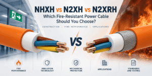
NHXH vs N2XH vs N2XRH: Which Fire-Resistant Power Cable Should You Choose?
NHXH vs N2XH vs N2XRH is an important comparison when specifying 0.6/1 kV power cables for emergency and life-safety systems. Although ...

How to Specify Low Current Cables for Infrastructure Projects
A professional low current cable specification should define much more than a cable name, conductor count or sheath colour. Infrastruct...

Fire Resistant Cables for Hospitals and High-Rise Buildings
Fire resistant cable for hospitals and high-rise buildings supports electrical, communication and control systems that may need to rema...
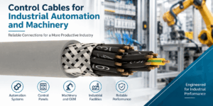
Industrial Control Cable Selection for Automation and Machinery
Industrial control cable selection should begin with the function of the circuit and the mechanical conditions of the machine rather th...
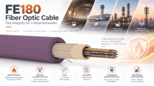
FE180 Fiber Optic Cable: Fire Integrity, Applications and Selection
An FE180 fiber optic cable is designed for optical communication routes where continued transmission during fire can form part of the p...
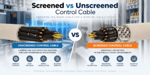
Screened vs Unscreened Control Cable: What Is the Difference?
Control cable shielding is one of the most important design decisions when selecting cable for industrial automation, machinery, buildi...

BMS Cable Selection: Building Automation Cables for HVAC and Smart Buildings
BMS cable selection should begin with the communication protocol and physical layer rather than with a generic request for “building au...


