





 President’s Message
Blog
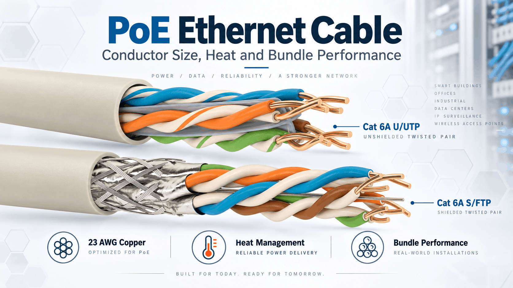
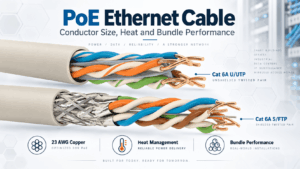
Ethernet Cable for PoE: Conductor Size, Heat and Bundle Performance
Reading Time: 16 minutes
A PoE Ethernet cable carries data and electrical power over the same balanced twisted-pair cabling system. This capability simplifies the connection of Wi-Fi access points, IP phones, building-automation devices, access-control equipment and other networked devices because the endpoint may not need a separate local power supply.
However, delivering power through copper conductors introduces an additional engineering issue that ordinary data-only Ethernet links do not face: heat. Electrical current flowing through conductor resistance generates power loss, and that loss appears as heat inside the cable.
Moreover, the effect becomes more important when installers place many powered Ethernet cables together in large bundles. Cables near the center of a bundle can dissipate heat less effectively than cables on the outside. Therefore, conductor size, DC resistance, ambient temperature, bundle size and cable construction all influence PoE cabling performance.
For example, a 23 AWG solid-copper conductor normally has lower electrical resistance than a thinner 24 AWG conductor of the same material and comparable construction. As a result, the larger conductor can reduce resistive losses and temperature rise when the cable carries higher PoE currents.
Nevertheless, cable category alone does not guarantee a particular conductor size or PoE performance. Engineers should review the actual cable datasheet, conductor gauge, DC resistance, temperature rating and installation conditions rather than assuming that every Cat 6 or Cat 6A cable behaves identically.
Quick answer: for demanding PoE installations, larger solid-copper conductors such as 23 AWG can provide lower resistance and reduced heating compared with thinner conductors. Cat 6A is frequently attractive for high-power PoE because many Cat 6A constructions use 23 AWG conductors and support high-performance structured cabling. However, the final cable selection must also consider bundle size, ambient temperature, cable temperature rating, shielding, category performance and the specific PoE power level.
PoE Ethernet Cable at a Glance
| Parameter | Why It Matters for PoE |
|---|---|
| Conductor material | Determines conductivity and resistance |
| Conductor size | Larger copper conductors generally reduce DC resistance and heat |
| 23 AWG vs 24 AWG | 23 AWG normally provides lower resistance for comparable construction |
| Solid vs stranded | Horizontal permanent cabling commonly uses solid conductors |
| DC resistance | Directly influences I²R power loss |
| DC resistance unbalance | Can influence current sharing between conductors and pairs |
| Bundle size | Larger bundles can retain more heat |
| Ambient temperature | Reduces the available temperature margin |
| Cable temperature rating | Defines the permitted operating range of the cable construction |
| Cat 6 vs Cat 6A | Cat 6A often uses larger conductors and provides higher transmission performance |
| Shielding | Influences EMI performance and can affect overall cable construction |
| PoE type | Higher power levels can increase conductor current and thermal load |
Consequently, a professional PoE specification should consider the electrical power function and the data-transmission function together.
What Is Power over Ethernet?
Power over Ethernet, commonly abbreviated as PoE, allows compatible network equipment to deliver DC electrical power through balanced Ethernet cabling while the same cabling carries data.
A PoE system typically contains:
- Power sourcing equipment, or PSE
- Balanced twisted-pair cabling
- Connecting hardware
- A powered device, or PD
For example, a PoE-capable Ethernet switch can provide both network connectivity and power to a wireless access point.
Therefore, the installation may avoid a separate AC outlet beside the access point.
In addition, centralized power delivery can simplify backup-power strategies because a UPS can support the network switch and, through PoE, the connected powered devices.
How PoE Has Increased in Power
PoE technology has evolved substantially since its first standardized implementation.
IEEE 802.3af introduced PoE with up to 15.4 W available from the power sourcing equipment.
Later, IEEE 802.3at increased the available PSE power to 30 W.
More recently, IEEE 802.3bt expanded remote power delivery by using all four pairs and supports substantially higher power, including Type 4 power levels up to 90 W at the PSE.
As a result, modern PoE networks can support equipment with much greater power demand than early IP phones.
Potential devices now include:
- Wi-Fi access points
- High-performance wireless equipment
- Pan-tilt-zoom devices
- Building automation controllers
- Access-control systems
- LED lighting equipment
- Thin clients
- IoT gateways
- Industrial Ethernet equipment
Consequently, cable thermal performance has become more important as PoE power levels have increased.
Why a PoE Ethernet Cable Generates Heat
Every copper conductor has electrical resistance.
When current flows through that resistance, part of the electrical energy converts into heat.
The basic relationship follows:
Power loss = I²R
where:
- I = electrical current
- R = conductor resistance
Therefore, heat loss increases with conductor resistance and rises rapidly as current increases because current is squared in the relationship.
For example, doubling conductor current does not merely double the resistive heating contribution. Under otherwise identical conditions, it produces four times the I²R loss.
For this reason, conductor resistance becomes especially relevant for higher-power PoE systems.
Conductor Size in a PoE Ethernet Cable
Conductor cross-section strongly influences cable resistance.
In the American Wire Gauge system, a lower AWG number represents a larger conductor.
Therefore:
- 22 AWG is larger than 23 AWG
- 23 AWG is larger than 24 AWG
- 24 AWG is larger than 26 AWG
A larger copper conductor normally offers lower resistance per unit length than a smaller copper conductor when other variables remain comparable.
Consequently, conductor size can influence:
- Voltage drop
- Power loss
- Temperature rise
- PoE efficiency
- Available power at the powered device
However, conductor gauge should never replace the actual electrical resistance value shown in the cable datasheet.
23 AWG vs 24 AWG for PoE Ethernet Cable
One of the most useful comparisons for PoE Ethernet cable selection is 23 AWG versus 24 AWG.
All else being equal, a 23 AWG copper conductor has a larger cross-sectional area than a 24 AWG conductor.
As a result, the 23 AWG construction generally provides lower DC resistance.
Lower resistance can mean:
- Lower conductor losses
- Reduced voltage drop
- Less heat generation
- Greater thermal margin
Therefore, 23 AWG cabling can become attractive in high-power PoE installations, particularly where many powered links run together.
Nevertheless, engineers should not select cable on AWG alone. Insulation material, cable diameter, temperature rating, pair construction and bundle arrangement also affect thermal performance.
Does Cat 6 Automatically Mean 23 AWG?
No universal rule makes every Cat 6 cable 23 AWG.
Manufacturers can design compliant products with different conductor dimensions provided that the completed cable satisfies the applicable electrical and transmission requirements.
Therefore, project engineers should inspect the datasheet rather than infer conductor size solely from the category.
ETK’s current Cat 6 F/UTP constructions, for example, use solid 23 AWG copper conductors.
However, another manufacturer or another Cat 6 product family can use a different design.
PoE Ethernet Cable and Cat 6A
PoE Ethernet cable specifications frequently favour Cat 6A for demanding new installations.
Cat 6A supports 10GBASE-T over the full structured-cabling channel length within its applicable standards framework and operates at frequencies up to 500 MHz.
Moreover, many Cat 6A horizontal cable constructions use relatively large solid copper conductors.
For example, ETK’s current Cat 6A U/UTP and S/FTP product families use 23 AWG solid copper conductors.
Consequently, Cat 6A can combine:
- High data capacity
- Low conductor resistance
- Strong future-proofing
- Improved alien-crosstalk performance
- Good suitability for high-density PoE infrastructure
Nevertheless, “Cat 6A” alone does not prove that every cable installation can support any bundle size or temperature condition. The specific cable and installation still require evaluation.
Cat 6 vs Cat 6A for PoE
Both Cat 6 and Cat 6A can support standardized PoE when the cabling meets the applicable electrical and installation requirements.
Therefore, the decision should not be reduced to the statement that Cat 6A is required for PoE.
Instead, Cat 6A becomes particularly attractive when a project combines:
- Higher PoE power
- Large numbers of powered endpoints
- Dense cable bundles
- Long service life
- 10 Gigabit Ethernet
- High-performance Wi-Fi
- Future network upgrades
By contrast, Cat 6 can remain a technically appropriate solution for many PoE applications when its conductor and thermal characteristics suit the installation.
Why Cable Bundles Matter for PoE
Individual Ethernet cables normally dissipate heat into their surroundings.
However, installers often group horizontal cabling together on trays, baskets, pathways and inside containment systems.
When many powered cables touch each other, cables near the center of the bundle cannot release heat as efficiently.
As a result, the internal bundle temperature can rise above the ambient temperature.
Several factors influence this temperature rise:
- Number of cables
- Conductor size
- PoE current
- Cable construction
- Ambient temperature
- Air movement
- Containment type
- Cable temperature rating
- How tightly installers group the cables
Therefore, bundle performance deserves specific attention in high-power PoE projects.
PoE Ethernet Cable Bundle Heating
Bundle heating does not mean that PoE cabling automatically creates an unsafe installation.
Instead, the engineering objective is to keep the conductors and completed cable within the temperature limits required by the cabling system and installation rules.
For example, Ethernet Alliance guidance notes that IEEE cabling expectations can involve a maximum 45°C ambient condition with an additional 15°C cable temperature rise, keeping the cabling within a 60°C data-transmission condition.
Accordingly, a cable installed in a hot ceiling void has less thermal margin than the same product installed in a cool telecommunications room.
Consequently, ambient temperature must form part of the PoE design.
Why the Center of a Cable Bundle Runs Hotter
Cables on the outside of a bundle have greater exposure to surrounding air.
By contrast, central cables sit behind several layers of neighbouring cables.
Those surrounding cables act as a thermal barrier.
Therefore, central cables can experience greater temperature rise.
This effect becomes more relevant as:
- Bundle diameter increases
- Current increases
- Ambient temperature rises
- Conductor resistance increases
For this reason, installers can improve thermal conditions by limiting bundle size or separating large cable groups where appropriate.
Large Bundles vs Smaller PoE Cable Bundles
Smaller bundles usually dissipate heat more easily than one very large, tightly packed bundle.
Therefore, dividing horizontal cabling into several smaller groups can improve thermal management.
For example, Ethernet Alliance installation guidance discusses groups of 24 cables as a practical way to simplify high-power PoE cabling management in appropriate installations.
However, installers must still follow the applicable electrical code, cabling standard, local regulations and project specification.
Consequently, “24 cables” should not be treated as a universal engineering limit for every country, cable and installation method.
PoE Ethernet Cable and Ambient Temperature
PoE Ethernet cable temperature consists of two basic components:
ambient temperature + temperature rise caused by current.
For example, imagine two identical cable bundles with the same PoE load.
One operates in a 20°C conditioned room.
The other operates inside a hot ceiling area at 40°C.
Even if both bundles experience the same current-related temperature rise, the second installation reaches a much higher final conductor temperature.
Therefore, designers should never evaluate PoE heating without considering the surrounding environment.
Cable Temperature Rating
Ethernet cables can carry different temperature ratings depending on their materials and construction.
A higher-rated cable can provide additional thermal margin where the installation conditions require it.
However, the network designer should not use a higher temperature rating as an excuse to ignore bundle design.
Instead, conductor size, cable rating, ambient conditions and bundle management should work together.
Moreover, elevated temperatures can influence data-transmission characteristics because conductor resistance rises as copper temperature increases.
Consequently, thermal design matters to both power delivery and network performance.
How Temperature Affects Copper Resistance
Copper resistance increases as conductor temperature rises.
Therefore, PoE cabling creates a feedback consideration:
current generates heat → temperature rises → copper resistance increases → resistive losses can increase.
Although structured-cabling standards account for operating temperature within their system requirements, engineers should still avoid unnecessary thermal stress.
For this reason, selecting low-resistance copper cabling and controlling bundle temperature can support more efficient power delivery.
Voltage Drop in a PoE Ethernet Cable
Voltage decreases as current travels through conductor resistance.
Therefore, higher resistance means greater voltage drop for the same current and link length.
This matters because the powered device receives less electrical power than the PSE launches into the cable.
In addition, PoE standards define system behaviour with cable losses in mind.
For example, IEEE Type 4 can provide up to 90 W at the PSE while the maximum power available to the PD is lower after accounting for the channel.
Consequently, lower cable resistance can reduce wasted energy and help maximize power-delivery efficiency.
Solid Copper vs Stranded Conductors for PoE
Permanent horizontal Ethernet cabling commonly uses solid copper conductors.
Patch cords, meanwhile, often use stranded conductors because repeated handling requires greater flexibility.
For an equivalent nominal conductor size and material, stranded constructions can exhibit different resistance characteristics from solid conductors.
Therefore, designers should evaluate the complete channel rather than only the horizontal cable.
However, this does not mean stranded patch cords are unsuitable for PoE. Standards-based structured cabling accounts for connecting hardware and cords within the channel design.
Why Copper Conductors Matter
Conductor material directly affects electrical resistance.
Professional PoE infrastructure should use cable constructions that satisfy the required structured-cabling standards and electrical performance.
ETK’s relevant Cat 6 and Cat 6A products use solid copper conductors.
Consequently, the cable provides both the electrical conductivity required for remote power and the controlled geometry required for Ethernet transmission.
Procurement teams should verify conductor material on the datasheet rather than relying on product appearance or jacket wording alone.
Why DC Resistance Matters in PoE Ethernet Cable
PoE Ethernet cable specifications should include attention to DC resistance rather than only frequency and data speed.
A cable can carry Ethernet data successfully while still creating unnecessary power losses if its conductor resistance is high.
Therefore, remote powering adds an electrical-power dimension to ordinary network-cable selection.
Lower resistance can support:
- Reduced heating
- Lower voltage drop
- Lower energy loss
- Greater PoE efficiency
However, resistance remains only one part of the complete cable specification.
DC Resistance Unbalance and PoE
PoE current does not simply depend on the average resistance of all eight conductors.
The resistance relationship between conductors and pairs also matters.
Excessive DC resistance unbalance can cause unequal current sharing.
As a result, one conductor or pair can carry more current than intended relative to another.
Therefore, high-quality balanced cable manufacturing requires tight control over conductor diameter, material consistency and pair construction.
Moreover, connector and termination quality can also influence resistance balance across the complete channel.
Four-Pair PoE and IEEE 802.3bt
IEEE 802.3bt expanded PoE by delivering power across all four balanced pairs.
This development enabled much higher power levels than earlier two-pair PoE systems.
Consequently, network cabling can now support devices with substantially greater electrical demand.
However, four-pair powering increases the importance of:
- Conductor resistance
- Resistance balance
- Thermal performance
- Bundle design
- Connector quality
Therefore, modern PoE planning should consider the cable as both a high-frequency transmission component and an electrical power-delivery path.
PoE Type 1, Type 2, Type 3 and Type 4
| PoE Type | Common IEEE Generation | Maximum PSE Power | Powered Pairs |
|---|---|---|---|
| Type 1 | IEEE 802.3af | 15.4 W | 2 pairs |
| Type 2 | IEEE 802.3at | 30 W | 2 pairs |
| Type 3 | IEEE 802.3bt | Up to 60 W | Up to 4 pairs |
| Type 4 | IEEE 802.3bt | Up to 90 W | 4 pairs |
As power increases, cable-loss and thermal considerations become progressively more important.
Therefore, cable selection that worked comfortably for an early low-power PoE phone network may not represent the best choice for a new high-power four-pair installation.
PoE Ethernet Cable for Wi-Fi Access Points
Wi-Fi access points represent one of the most important modern PoE Ethernet cable applications.
Higher-performance access points can require both greater network bandwidth and higher electrical power.
Consequently, Cat 6A becomes attractive because it can support 10 Gigabit Ethernet while also offering robust copper conductor constructions for remote power.
In addition, ceiling-mounted access points often create large groups of horizontal cables returning to telecommunications rooms.
Therefore, designers should consider PoE bundle heating together with the bandwidth requirements of the wireless network.
PoE Ethernet Cable for Building Automation
Building infrastructure increasingly connects devices directly to Ethernet networks.
Potential PoE-powered equipment can include:
- Controllers
- Sensors
- Access devices
- Room equipment
- IoT gateways
- Lighting controllers
As a result, a smart building can contain hundreds or thousands of remotely powered Ethernet links.
Therefore, aggregate bundle conditions can matter even when the power requirement of one individual device appears modest.
PoE Ethernet Cable for Industrial Networks
Industrial facilities create additional considerations because ambient temperature and electromagnetic interference can be higher than in ordinary offices.
For example, cable routes can pass near:
- Motors
- Variable-frequency drives
- Power cables
- Transformers
- Industrial equipment
Consequently, screened Ethernet constructions can become useful for signal integrity.
Meanwhile, the PoE design still needs to consider conductor resistance and temperature.
Therefore, shielding and PoE thermal performance should remain separate but coordinated specification requirements.
Shielded vs Unshielded PoE Ethernet Cable
Both screened and unscreened balanced cabling can support PoE when the products satisfy the relevant standards.
Shielding primarily addresses electromagnetic compatibility rather than creating PoE capacity.
Common constructions include:
- U/UTP
- F/UTP
- U/FTP
- S/FTP
For instance, S/FTP can provide strong protection against external electromagnetic interference and pair-to-pair interaction.
However, engineers should select shielding according to the EMI environment and transmission requirements rather than assume that shielded cable automatically runs cooler.
Does a Larger Cable Always Mean Better PoE Performance?
No.
Overall cable diameter can increase because of several design elements, including:
- Larger conductors
- Thicker insulation
- Pair separators
- Foil screens
- Braid screens
- Outer sheath thickness
Therefore, cable outside diameter alone does not reveal conductor resistance.
Instead, buyers should compare actual conductor gauge and DC resistance data.
PoE Ethernet Cable and Connector Heating
The cable is not the only component carrying PoE current.
RJ45 connectors, patch panels, keystone jacks and patch cords also form part of the powered channel.
Therefore, connection quality matters.
Poor or contaminated contacts can increase contact resistance, while repeated disconnection under electrical load can stress connector contacts.
Consequently, the complete PoE channel should use connecting hardware appropriate for the required category and remote-power application.
PoE and Cable Length
A longer copper link contains more conductor resistance than a shorter link of the same construction.
As a result, longer runs create greater voltage drop and resistive power loss.
Structured Ethernet cabling standards already define maximum channel and permanent-link configurations.
However, PoE designers can still benefit from efficient route planning that avoids unnecessary cable length.
Therefore, minimizing excessive routing supports both data and power efficiency.
Why High Temperature Can Affect Data Performance
PoE heating does not only concern electrical power.
Copper resistance rises with temperature, and increased resistance contributes to additional insertion loss.
Therefore, elevated cable temperature can reduce transmission margin.
This effect becomes particularly relevant on longer high-frequency channels.
Consequently, thermal management helps protect both remote-power performance and Ethernet data performance.
PoE Ethernet Cable and ISO/IEC 29125
ISO/IEC TS 29125 provides specific guidance for remote powering over balanced telecommunications cabling.
The document addresses topics including:
- Cabling selection
- Ambient temperature
- Temperature rise
- Current-carrying capacity
- Bundle size
- Installation conditions
- Mitigation options
Therefore, it provides a particularly relevant framework when designers move beyond ordinary data transmission and use structured cabling to deliver significant electrical power.
Moreover, the specification has received subsequent amendments, including an Amendment 2 published in 2024.
PoE Ethernet Cable and ISO/IEC 11801
PoE Ethernet cable still needs to satisfy the normal structured-cabling requirements of the network.
ISO/IEC 11801 provides the generic-cabling framework for customer premises.
Consequently, PoE does not replace category, channel or transmission-performance requirements.
Instead, remote powering adds another set of electrical and thermal considerations to the balanced cabling system.
The ISO/IEC 11801-1 framework also received an amendment published in 2025, so project specifications should reference the applicable current documents rather than automatically copying older tender text.
TIA Guidance for PoE Cable Bundles
TIA TSB-184-A provides guidance for supporting power delivery over balanced twisted-pair cabling.
The guidance addresses higher-current PoE installations and considerations such as:
- Bundle size
- Cable gauge
- Installation conditions
- Current levels
- Patch cords
- Temperature
Therefore, designers working under TIA-based structured-cabling specifications should consider PoE guidance alongside the main balanced-cabling requirements.
Common PoE Ethernet Cable Specification Mistakes
Choosing Cable Only by Ethernet Category
Cat 6 or Cat 6A identifies transmission performance, but PoE planning should also review conductor size, resistance and temperature characteristics.
Assuming Every Cat 6 Cable Uses 23 AWG
Manufacturers can use different compliant constructions. Therefore, buyers should verify conductor size on the datasheet.
Assuming Cat 6A Automatically Solves Every PoE Thermal Issue
Cat 6A can offer excellent PoE characteristics, but bundle size, ambient temperature and cable rating still matter.
Ignoring Bundle Size
Large bundles can retain more heat, particularly around cables near the center.
Ignoring Ambient Temperature
A cable bundle in a hot ceiling void has less thermal margin than the same bundle in a conditioned room.
Using Conductor Gauge Without Checking Resistance
AWG provides useful construction information, but the datasheet DC resistance gives a more direct electrical parameter.
Ignoring DC Resistance Unbalance
Unequal resistance can affect current sharing across powered pairs.
Assuming Shielding Determines PoE Capability
Shielding primarily addresses electromagnetic performance. Conductor and thermal parameters determine PoE losses.
Ignoring Patch Cords and Connectors
The entire channel carries current, so connecting hardware and cords also influence the powered link.
Using Non-Standard Remote Power Systems Without Review
Non-standard powering can operate outside IEEE PoE assumptions and therefore requires separate electrical assessment.
Ignoring Future PoE Upgrades
A network installed for low-power devices today can later serve higher-power equipment.
Selecting Cable Only by Price
A lower-cost cable with higher resistance can increase electrical losses and reduce thermal margin over the network’s service life.
How to Select a PoE Ethernet Cable
Identify the PoE Power Level
Start by determining whether the powered equipment uses Type 1, Type 2, Type 3 or Type 4 PoE.
Check the Network Speed
Next, define whether the link requires 1 Gigabit, 2.5/5 Gigabit or 10 Gigabit Ethernet.
Verify Conductor Material
Confirm that the product uses the conductor construction required by the project and applicable standards.
Compare Conductor Size
Review 23 AWG, 24 AWG or another specified construction together with actual resistance values.
Review DC Resistance
Use the cable datasheet to compare electrical losses rather than relying on category alone.
Check Resistance Balance
Ensure that the cable and complete channel satisfy the applicable DC resistance-unbalance requirements.
Assess Bundle Size
Determine how many powered cables will run together through trays, baskets, conduits or other containment.
Review Ambient Temperature
Consider ceiling voids, industrial areas and other locations where ambient temperature can exceed normal room conditions.
Check Cable Temperature Rating
Confirm that the complete cable construction provides sufficient thermal margin for the installation.
Select the Appropriate Category
Choose Cat 6, Cat 6A or another category according to bandwidth, PoE, future capacity and project requirements.
Evaluate Shielding
Select U/UTP, F/UTP, U/FTP, S/FTP or another construction according to the electromagnetic environment.
Verify Fire Performance
Specify PVC, LSZH and any CPR requirements separately from PoE performance.
Review Connecting Hardware
Use connectors, patch panels and patch cords suitable for the category and required remote-power application.
Verify Standards and Documentation
Finally, review test reports and datasheets against the applicable ISO/IEC, IEEE, TIA and project requirements.
PoE Ethernet Cable RFQ Checklist
A professional PoE Ethernet cable RFQ should contain enough information for manufacturers to evaluate both data and remote-power performance.
Useful requirements include:
- Ethernet category
- Required data rate
- PoE type or maximum powered-device requirement
- Solid copper conductor
- Conductor gauge
- Maximum DC resistance
- DC resistance unbalance requirements
- U/UTP, F/UTP, U/FTP or S/FTP construction
- Maximum frequency
- Characteristic impedance
- Insertion-loss requirements
- NEXT requirements
- Return-loss requirements
- Alien-crosstalk requirements where applicable
- Maximum cable diameter
- Temperature rating
- Expected ambient temperature
- Expected bundle size
- PVC, LSZH or PE sheath
- CPR class where applicable
- Indoor or outdoor installation
- UV resistance where required
- Applicable structured-cabling standards
- Required test documentation
- Packing length
- Cable marking
Consequently, procurement teams can compare technically equivalent cables rather than treating every cable carrying the same category marking as identical.
ETK Kablo Solutions for PoE Networks
ETK Kablo manufactures Data/LAN cable families for enterprise, data-center, industrial and building-network applications.
The current portfolio includes:
Depending on category, ETK offers shielding constructions including U/UTP, F/UTP, U/FTP, F/FTP and S/FTP, together with PVC, LSZH and PE sheath options for different environments.
For example, ETK’s Cat 6 F/UTP family uses solid 23 AWG copper conductors. Likewise, its current Cat 6A U/UTP and S/FTP constructions use solid 23 AWG copper conductors.
Therefore, relevant ETK Cat 6 and Cat 6A constructions can provide the low-resistance copper architecture that engineers frequently seek for modern PoE infrastructure.
However, ETK recommends matching the specific cable construction to the required category, PoE load, electromagnetic environment, fire requirements and installation conditions rather than selecting cable from category name alone.
Frequently Asked Questions About PoE Ethernet Cable
What is the best Ethernet cable for PoE?
The correct cable depends on PoE power, network speed, conductor size, resistance, bundle size and installation temperature. Cat 6A with solid 23 AWG copper conductors is a strong option for many demanding new installations.
Can Cat 6 carry PoE?
Cat 6 can support standardized PoE when the cable and complete installation satisfy the relevant electrical, thermal and cabling requirements.
Is Cat 6A better for PoE?
Cat 6A can offer useful advantages for demanding PoE projects, including larger conductors in many product designs, 10GBASE-T support and strong alien-crosstalk performance.
Is 23 AWG better than 24 AWG for PoE?
For otherwise comparable copper constructions, 23 AWG generally provides lower electrical resistance and therefore lower resistive loss than 24 AWG.
Does thicker Ethernet cable reduce heat?
Larger copper conductors can reduce resistance-related heating, but overall thermal performance also depends on current, ambient temperature, bundle size and cable construction.
Why do PoE cable bundles get hot?
Electrical current produces I²R losses, while cables in the center of large bundles dissipate that heat less effectively.
Does PoE damage Ethernet cable?
A correctly designed standards-based PoE installation should operate within the electrical and temperature limits of its cabling system.
Does PoE reduce Ethernet speed?
PoE and Ethernet data operate simultaneously over the cabling. Proper standards-compliant PoE does not inherently reduce the specified Ethernet data rate.
Does cable temperature affect data performance?
Higher copper temperature increases resistance and can increase insertion loss, so temperature forms part of structured-cabling performance considerations.
Can U/UTP cable support PoE?
U/UTP can support PoE when the cable meets the applicable category, electrical and thermal requirements.
Can S/FTP support PoE?
S/FTP can also support PoE. Its additional screening primarily improves electromagnetic performance rather than creating the remote-power capability itself.
Does PoE require shielded cable?
Not universally. Shielding should follow EMI and structured-cabling requirements rather than PoE alone.
What is four-pair PoE?
Four-pair PoE uses all four balanced pairs to deliver power and enables higher power levels under IEEE 802.3bt.
How much power can PoE++ deliver?
Terminology varies commercially, but IEEE 802.3bt Type 4 supports up to 90 W from the power sourcing equipment.
Why is DC resistance important for PoE?
Higher resistance increases voltage drop and I²R power loss, which reduces efficiency and increases conductor heating.
What is DC resistance unbalance?
It describes differences in resistance between conductors or pairs that can cause unequal current sharing in a powered balanced-cabling channel.
Should PoE cables be installed in smaller bundles?
Smaller bundles can improve heat dissipation. However, the exact bundle design should follow the applicable cabling standard, electrical code, cable specification and project conditions.
Can existing Ethernet cable support higher-power PoE?
Potentially, but engineers should review the installed cable category, conductor size, temperature rating, bundle conditions and remote-power requirements before upgrading.
Does cable length affect PoE?
Yes. Longer copper conductors create more resistance, which increases voltage drop and power loss.
How should PoE Ethernet cable be selected?
Start with the PoE power requirement and network speed, then evaluate conductor size, resistance, bundle size, temperature, shielding, fire performance and connecting hardware.
Conclusion
A PoE Ethernet cable performs two jobs simultaneously: high-frequency data transmission and electrical power delivery.
Therefore, selecting the cable only by Ethernet category leaves important engineering questions unanswered.
Conductor size matters because lower-resistance copper conductors reduce voltage drop and I²R losses. For this reason, 23 AWG solid-copper constructions can provide useful thermal and efficiency advantages over thinner conductors in demanding PoE installations.
Meanwhile, cable bundles create an additional challenge. As more powered cables run together, heat dissipation becomes more difficult, especially for cables in the center of the bundle.
Consequently, ambient temperature, bundle size and cable temperature rating must be considered together.
Choose PoE Cabling for Power and Data Together
Engineers should first define the PoE power level and network bandwidth.
Next, conductor gauge and actual DC resistance should determine whether the cable provides sufficient electrical efficiency.
Afterward, bundle size, ambient temperature and cable temperature rating should establish the thermal margin.
Finally, category performance, shielding, fire requirements and connecting hardware should complete the structured-cabling specification.
Ultimately, the best PoE cabling system is not simply the cable with the highest category number. It is the balanced-cabling system whose data performance, copper resistance, thermal characteristics and installation conditions match the actual remote-power requirement.
Benzer yazılar
Ethernet Cable Testing: NEXT, Return Loss, Insertion Loss and ACR Explained
Ethernet cable testing verifies whether a twisted-pair copper cabling system can transmit data within the electrical performance limits...

Fiber Optic Cable Attenuation: 850, 1310, 1550 and 1625 nm Explained
Fiber optic cable attenuation describes the reduction in optical power as light travels through an optical fiber. It is normally expres...
A-02YSF(L)2Y vs A-2Y(L)2Y Outdoor Telephone Cable
A-02YSF(L)2Y vs A-2Y(L)2Y is an important comparison when selecting copper outdoor telephone cable for telecommunications networks, und...
RS-485 Cable vs Instrumentation Cable: Can Instrumentation Cable Be Used for Modbus RTU?
A Modbus RTU cable must do more than carry a low-voltage digital signal from one device to another. Modbus RTU commonly uses an RS-485 ...
Ethernet Cable for PoE: Conductor Size, Heat and Bundle Performance
A PoE Ethernet cable carries data and electrical power over the same balanced twisted-pair cabling system. This capability simplifies t...
NHXH vs N2XH vs N2XRH: Which Fire-Resistant Power Cable Should You Choose?
NHXH vs N2XH vs N2XRH is an important comparison when specifying 0.6/1 kV power cables for emergency and life-safety systems. Although ...

How to Specify Low Current Cables for Infrastructure Projects
A professional low current cable specification should define much more than a cable name, conductor count or sheath colour. Infrastruct...

Fire Resistant Cables for Hospitals and High-Rise Buildings
Fire resistant cable for hospitals and high-rise buildings supports electrical, communication and control systems that may need to rema...

Industrial Control Cable Selection for Automation and Machinery
Industrial control cable selection should begin with the function of the circuit and the mechanical conditions of the machine rather th...

FE180 Fiber Optic Cable: Fire Integrity, Applications and Selection
An FE180 fiber optic cable is designed for optical communication routes where continued transmission during fire can form part of the p...

Screened vs Unscreened Control Cable: What Is the Difference?
Control cable shielding is one of the most important design decisions when selecting cable for industrial automation, machinery, buildi...

BMS Cable Selection: Building Automation Cables for HVAC and Smart Buildings
BMS cable selection should begin with the communication protocol and physical layer rather than with a generic request for “building au...


