





 President’s Message
Blog
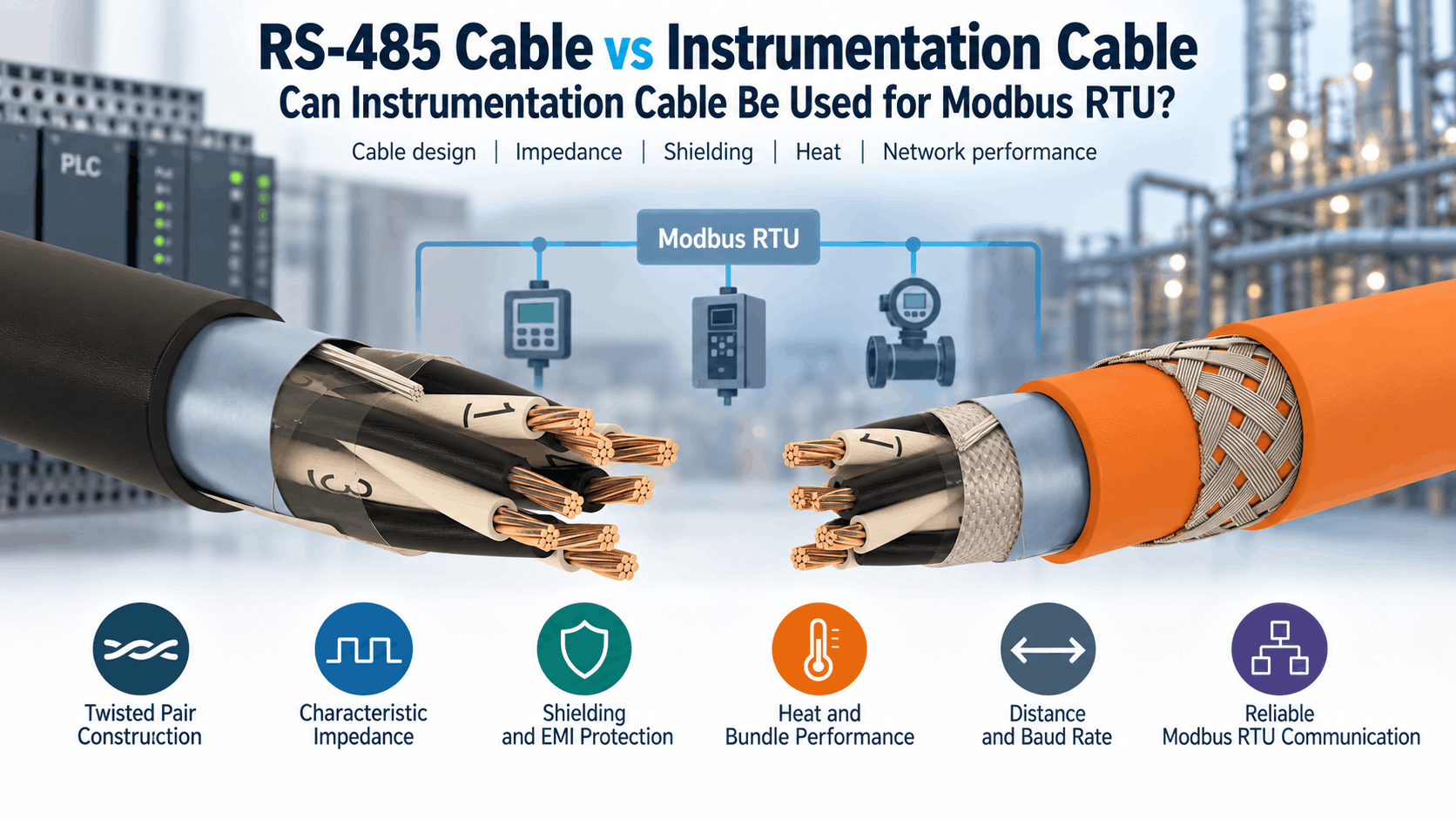
RS-485 Cable vs Instrumentation Cable: Can Instrumentation Cable Be Used for Modbus RTU?
Reading Time: 17 minutes
A Modbus RTU cable must do more than carry a low-voltage digital signal from one device to another. Modbus RTU commonly uses an RS-485 physical layer, which relies on balanced differential transmission, controlled cable geometry, appropriate termination and careful bus topology to maintain reliable communication across industrial networks.
Because many instrumentation cables also use twisted pairs and an overall screen, engineers often ask whether a dedicated RS-485 cable is really necessary. In some installations, a suitable instrumentation cable can work successfully. However, the answer depends on the cable’s electrical characteristics rather than its product family name.
For example, a screened instrumentation cable can contain the correct copper conductor size and pair construction yet still lack a declared characteristic impedance. Another cable can have acceptable capacitance but use a core arrangement that was designed for analogue measurement circuits rather than balanced digital transmission.
Therefore, a cable should not be approved for Modbus RTU simply because its datasheet says “instrumentation cable,” “twisted pair” or “screened.” Engineers should verify characteristic impedance, capacitance, conductor resistance, pair geometry, shielding and the actual network distance and baud rate.
Quick answer: instrumentation cable can be used for Modbus RTU only when its construction and electrical characteristics suit RS-485 communication. For two-wire Modbus, the official Modbus serial-line guide calls for a shielded balanced pair for D0-D1 plus a common conductor. Characteristic impedance above 100 Ω is preferred, especially at 19,200 baud and higher. Therefore, a purpose-designed RS-485 cable is the safer choice when impedance, capacitance and long-distance performance cannot be confirmed for the instrumentation cable.
Modbus RTU Cable at a Glance
| Parameter | RS-485 / Modbus RTU Requirement | Typical Instrumentation Cable |
|---|---|---|
| Balanced pair | Required for D0-D1 | Available in pair constructions |
| Common conductor | Required by Modbus serial-line guidance | Must be available separately |
| Shield | Required by Modbus guidance | Commonly available |
| Characteristic impedance | Above 100 Ω preferred, especially at higher baud rates | Often not declared |
| Capacitance | Lower values generally support longer/high-speed links | Varies significantly |
| Twisted pair | Required for differential transmission | Available in TP designs |
| Conductor gauge | Must suit required network length | Often 0.5–2.5 mm² |
| Termination | Required at both ends of the trunk | Cable must suit the transmission line |
| Topology | Trunk / daisy-chain with short derivations | Independent of cable family |
| Best use | Digital RS-485 communication | Analogue/digital instrumentation and control |
Consequently, the fact that two cables look similar does not mean that their transmission performance is equivalent.
What Is RS-485?
RS-485 defines an electrical interface for balanced digital multipoint communication.
Instead of transmitting information as a voltage referenced only to ground, RS-485 uses a differential signal across a balanced pair.
The receiver evaluates the voltage difference between the two signal conductors.
As a result, RS-485 can provide strong immunity to electromagnetic interference in industrial environments.
Typical applications include:
- PLC networks
- Building automation
- Industrial controllers
- Energy meters
- Variable-frequency drives
- Remote I/O
- Process equipment
- HVAC controllers
- Industrial gateways
However, RS-485 itself does not define the application protocol carried over the cable.
What Is Modbus RTU?
Modbus RTU is a serial communication protocol widely used in industrial automation and building-control systems.
It defines how devices structure, address and exchange Modbus messages.
Meanwhile, RS-485 commonly provides the underlying electrical transmission system.
Therefore, the two terms describe different layers:
- Modbus RTU = communication protocol
- RS-485 = electrical physical layer
Consequently, engineers should avoid using “RS-485” and “Modbus RTU” as though they were identical technologies.
Why Modbus RTU Cable Construction Matters
A Modbus RTU cable forms a transmission line rather than merely an electrical connection.
Digital signal edges travel along the cable and can reflect when they encounter impedance discontinuities.
Those reflections can distort the transmitted waveform and reduce communication reliability.
Therefore, parameters such as characteristic impedance become increasingly important as baud rate and network length increase.
In addition, excessive cable capacitance can slow signal transitions.
Consequently, long Modbus networks require greater attention to cable transmission characteristics than short, low-speed connections.
RS-485 Cable vs Instrumentation Cable: The Main Difference
The primary difference between dedicated RS-485 cable and ordinary instrumentation cable is the design objective.
A purpose-designed RS-485 cable controls parameters such as:
- Pair geometry
- Characteristic impedance
- Capacitance
- Conductor resistance
- Shielding
Instrumentation cable, meanwhile, is commonly designed to transmit analogue or low-frequency digital signals between field instruments and control systems.
Typical instrumentation circuits include:
- 4–20 mA loops
- Temperature transmitters
- Pressure transmitters
- Flow meters
- Process sensors
- Control signals
Therefore, instrumentation cable can possess many characteristics that are useful for RS-485 without necessarily being optimized for RS-485 transmission.
Can Instrumentation Cable Be Used as Modbus RTU Cable?
Yes, but only when the actual cable meets the requirements of the network.
A suitable instrumentation cable should provide at least:
- A balanced twisted pair
- Suitable characteristic impedance
- Acceptable capacitance
- Sufficient conductor size
- Screening
- A suitable common conductor arrangement
- Appropriate environmental performance
Moreover, the required performance depends on the baud rate, network length, device loading and topology.
Therefore, a cable that performs reliably over 50 metres at 9,600 baud might not provide the same reliability over several hundred metres at a higher baud rate.
Balanced Pair Requirements for Modbus RTU Cable
A Modbus RTU cable should use a balanced pair for the D0 and D1 signals.
The official Modbus serial-line implementation guide specifies one balanced pair for a two-wire RS-485 Modbus network together with a common conductor.
For four-wire Modbus, an additional balanced pair carries the second differential signal path.
Therefore, cables with individually twisted pairs are generally much more appropriate than cables whose conductors are simply stranded together in layers.
This distinction is particularly important when comparing instrumentation constructions.
Pair Construction vs Layer-Stranded Instrumentation Cable
Not every instrumentation cable uses twisted pairs.
Some multicore instrumentation designs arrange insulated conductors together in layers.
That construction can work very well for certain control or instrumentation circuits.
However, it does not automatically create the balanced geometry expected by RS-485.
By contrast, TP instrumentation constructions explicitly twist the conductors into pairs.
Consequently, a pair-constructed instrumentation cable is a much more logical candidate for Modbus RTU than a generic layer-stranded multicore cable.
Characteristic Impedance in Modbus RTU Cable
Characteristic impedance is one of the most important parameters in a Modbus RTU cable.
It describes the electrical behaviour of the transmission line as a travelling signal propagates along the pair.
According to the Modbus serial-line implementation guide, a characteristic impedance above 100 Ω can be preferred for RS-485 balanced pairs, particularly at 19,200 baud and higher.
Many dedicated RS-485 cable designs use nominal impedance values around 120 Ω.
However, the exact value should follow the network and equipment specification rather than being assumed universally.
Therefore, a cable datasheet that does not state characteristic impedance requires additional verification before engineers treat that cable as an RS-485 transmission cable.
Why 120 Ohms Is Commonly Associated with RS-485
Many RS-485 systems use cable with a nominal characteristic impedance around 120 Ω.
For that reason, 120 Ω termination resistors are also common in practical networks.
However, Modbus guidance allows different termination arrangements depending on the system.
The official implementation guide notes that line termination may use 150 Ω and also discusses a 120 Ω resistor with a series capacitor in particular polarization arrangements.
Therefore, engineers should follow the connected-device and system documentation rather than apply 120 Ω termination blindly to every installation.
Why Termination Is Required
Signal reflections occur when a travelling electrical wave encounters a discontinuity in transmission-line impedance.
At sufficiently high speed or long distance, these reflections can distort the communication signal.
Therefore, RS-485 buses normally use termination near both ends of the trunk.
The Modbus implementation guide requires termination at both trunk extremities and warns against placing additional line terminations on derivation cables.
Consequently, termination belongs to the network architecture rather than simply to the cable specification.
Capacitance in Modbus RTU Cable
Capacitance also influences digital communication performance.
Every twisted pair has capacitance between its conductors and surrounding elements.
Higher capacitance increases the electrical load on the driver.
As a result, signal edges can become slower over long cable distances.
Therefore, lower-capacitance cable generally provides greater flexibility for long-distance or higher-speed RS-485 networks.
Nevertheless, capacitance should not be evaluated alone.
Characteristic impedance, conductor resistance and transceiver characteristics all influence the final communication system.
Instrumentation Cable Capacitance and Modbus RTU
Instrumentation cables can have substantially different capacitance values depending on insulation material and construction.
For example, PE-insulated pair-type instrumentation cable often provides lower capacitance than some XLPE or HFFR designs.
However, a low capacitance figure alone does not prove RS-485 suitability.
The pair still needs the appropriate balanced geometry and characteristic impedance.
Consequently, engineers should avoid selecting instrumentation cable for Modbus RTU based only on the lowest capacitance value in a catalogue.
PE vs XLPE Insulation for RS-485 Communication
Insulation material affects cable dielectric characteristics.
Polyethylene has favourable electrical properties and is widely used in communication cable designs.
Therefore, PE-insulated instrumentation cables can be attractive candidates where digital transmission performance is important.
XLPE, meanwhile, provides strong thermal and mechanical properties and is widely used in industrial instrumentation cable.
However, the finished cable geometry ultimately determines characteristic impedance and capacitance.
Consequently, insulation material should support the required transmission characteristics rather than replace them.
Conductor Size in Modbus RTU Cable
The Modbus implementation guide states that conductor gauge should be large enough to permit the required network length.
It also notes that AWG 24 is sufficient for Modbus data and provides an example of up to 1,000 metres at 9,600 baud using AWG 26 or larger conductors under the specified conditions.
Therefore, larger instrumentation conductors such as 0.50 mm², 0.75 mm² or 1.0 mm² can easily provide adequate conductor cross-section from a resistance perspective.
However, using a very large conductor does not automatically improve high-frequency transmission.
Again, impedance and capacitance remain critical.
Does Larger Instrumentation Cable Mean Better Modbus Performance?
No.
A larger conductor can reduce DC resistance.
However, cable diameter and conductor cross-section do not determine characteristic impedance by themselves.
For example, a 1.5 mm² instrumentation pair can have excellent low resistance but still possess transmission characteristics that are less suitable for a high-speed RS-485 bus than a smaller purpose-designed communication pair.
Therefore, engineers should choose conductor size according to the complete transmission-line design rather than the assumption that bigger is always better.
Shielding in Modbus RTU Cable
The official Modbus serial-line guide specifies shielded cable.
Screening helps protect the balanced signal from external electromagnetic interference.
Common shield constructions include:
- Aluminium/polyester foil
- Copper braid
- Foil plus braid
- Individual pair screens
- Overall screens
For many industrial Modbus installations, an overall foil screen with a drain wire can provide effective protection.
Meanwhile, especially noisy environments can justify more robust screen constructions.
Instrumentation Cable Shielding for RS-485
Instrumentation cable often already includes an overall aluminium/polyester screen and drain wire.
Therefore, shielding is one area where instrumentation cable frequently resembles dedicated RS-485 cable.
However, electromagnetic screening and balanced transmission are different functions.
A screened cable can still have unsuitable impedance or pair geometry.
Consequently, the presence of foil screening should never be treated as proof of Modbus compatibility.
Overall Screen vs Individually Screened Pairs
RS-485 normally communicates over one balanced differential pair.
Therefore, individual pair screening is not automatically necessary.
An overall screen can provide adequate electromagnetic protection for many installations.
However, multi-pair cables carrying several independent signal systems can benefit from additional separation between circuits.
Consequently, PiMF-style instrumentation constructions can become relevant where multiple sensitive pairs occupy the same cable.
Nevertheless, the communication equipment specification should determine whether that complexity is required.
Modbus RTU Cable in High-EMI Environments
Modbus RTU cable frequently operates inside industrial facilities with significant electromagnetic noise.
Potential interference sources include:
- Variable-frequency drives
- Motors
- Large contactors
- Transformers
- Power cables
- Switchgear
- Welding equipment
Therefore, cable selection should combine balanced-pair construction with effective shielding.
In addition, cable routing remains important.
Even a well-screened communication cable benefits from sensible separation from high-power electrical circuits.
RS-485 Bus Topology for Modbus RTU
RS-485 Modbus should generally use a trunk or daisy-chain architecture.
Devices connect along the main bus directly or through short derivations.
The Modbus implementation guide states that the two ends of the trunk require line termination.
Meanwhile, derivation cables should remain short.
Therefore, star wiring can create unnecessary branches and impedance discontinuities.
Consequently, many communication problems blamed on the cable are actually topology problems.
Maximum Modbus RTU Cable Length
There is no single network length that applies to every RS-485 Modbus installation.
Maximum distance depends on:
- Baud rate
- Conductor gauge
- Capacitance
- Characteristic impedance
- Number of connected loads
- Network topology
- Transceiver design
The Modbus implementation guide gives 1,000 metres as an example maximum trunk length at 9,600 baud using AWG 26 or larger conductors under its stated conditions.
Therefore, engineers should not take “1,000 metres” as a universal guarantee for every instrumentation cable and network configuration.
Why Baud Rate Matters
Higher baud rates shorten the time available for each transmitted bit.
As a result, reflections, capacitance and waveform distortion become more significant.
For this reason, Modbus guidance places greater emphasis on suitable characteristic impedance at 19,200 baud and above.
Consequently, a generic instrumentation cable that works reliably at 9,600 baud may become less appropriate as communication speed increases.
9,600 vs 19,200 vs 38,400 Baud
Lower-speed Modbus networks generally tolerate cable imperfections more easily than faster networks.
At 9,600 baud, an appropriately constructed cable can support long communication distances.
Once the network reaches 19,200 baud and above, controlled impedance becomes more important.
For still higher baud rates, network length and stub length usually become more restrictive.
Therefore, cable selection should always reflect the configured communication speed rather than one generic “Modbus cable” requirement.
Modbus RTU Cable and Stub Length
Short derivation cables connect devices to the main RS-485 trunk when direct daisy chaining is not possible.
However, every branch creates an impedance discontinuity.
The Modbus guide therefore limits derivations and recommends keeping them short.
For a normal passive derivation, the guide specifies a maximum of 20 metres.
Meanwhile, multi-port taps impose additional restrictions based on the number of derivations.
Consequently, network designers should not solve poor device placement by creating long star branches.
Modbus RTU Cable and Common Conductor
A two-wire Modbus network still requires more than the two differential data conductors.
The Modbus serial-line guide specifies a third conductor for the signal common.
Therefore, a simple one-pair cable containing only two insulated wires can be insufficient for a standards-oriented installation unless the required common path is provided separately.
This point is particularly important when evaluating instrumentation cables.
Consequently, the cable construction should provide the appropriate conductors for D0, D1 and Common.
Two-Wire vs Four-Wire Modbus RTU Cable
Most modern Modbus RTU RS-485 installations use a two-wire architecture.
In this configuration, the same balanced pair handles transmission in both directions.
Four-wire systems use separate transmit and receive pairs.
Therefore, four-wire Modbus requires a second balanced pair in addition to the common conductor.
Moreover, each balanced pair requires appropriate termination at the relevant bus ends.
Consequently, cable-core requirements change according to the network architecture.
Can Cat 5 Cable Be Used for Modbus RTU?
The Modbus implementation guide recognizes that Category 5 cable can operate for RS-485 Modbus.
However, it gives a shorter maximum distance of 600 metres in that context.
In addition, connectorized Category 5 systems require careful wiring because crossed connections can create problems in a two-wire Modbus system.
Therefore, Ethernet-category cable can function in some RS-485 applications without necessarily being the best industrial Modbus cable choice.
Environmental durability, shielding and installation conditions still matter.
RS-485 Cable vs Ethernet Cable
RS-485 and Ethernet use balanced transmission, but they have different physical-layer requirements.
Ethernet cables are optimized for high-frequency data transmission according to categories such as Cat 5e, Cat 6 and Cat 6A.
RS-485 cable, meanwhile, is optimized for serial differential communication with its own impedance, topology and termination requirements.
Therefore, cable families should not be treated as interchangeable simply because both contain twisted pairs.
RS-485 Cable vs KNX Cable
KNX TP cable also uses balanced copper communication and commonly has an impedance range around 100–120 Ω depending on construction.
However, KNX and RS-485 represent different communication systems.
KNX cable can have a star-quad architecture and electrical parameters developed specifically for the KNX bus.
Therefore, the presence of approximately suitable impedance does not automatically make a KNX cable the preferred Modbus RTU solution.
The complete cable construction and equipment requirements still need verification.
RS-485 Cable vs Control Cable
General control cables commonly use multicore constructions for relay commands, digital I/O and actuator circuits.
Some screened control cables provide useful EMI protection.
However, ordinary control cable frequently lacks a defined characteristic impedance.
Therefore, it should not automatically replace a dedicated RS-485 communication cable.
For short, low-speed links, some constructions may work in practice, but a professional specification should rely on verified electrical characteristics rather than successful trial-and-error communication.
RS-485 Cable vs Instrumentation Cable for 4–20 mA
A 4–20 mA analogue loop and an RS-485 digital bus have different transmission requirements.
Instrumentation cable for 4–20 mA commonly emphasizes:
- Low conductor resistance
- Pair twisting
- Screening
- Capacitance
- Mechanical protection
Those same characteristics can be helpful for RS-485.
However, RS-485 additionally benefits from controlled characteristic impedance because it operates as a digital transmission line.
Consequently, a cable excellent for a 4–20 mA loop is not automatically an ideal Modbus RTU cable.
EN 50288-7 Instrumentation Cable and Modbus RTU
EN 50288-7 covers relevant multi-element metallic instrumentation and control cable constructions.
Such cables can provide pairs, triads, screens, armour and different insulation systems.
However, EN 50288-7 compliance does not automatically mean that a cable has the characteristic impedance required for a particular RS-485 network.
Therefore, the specific product datasheet still needs to confirm the relevant transmission parameters.
This distinction is important when consultants write specifications containing both “EN 50288-7” and “Modbus RTU.”
ETK Instrumentation Cable as Modbus RTU Cable
ETK Kablo manufactures several pair and triad instrumentation-cable families under EN 50288-7.
For example, RE-2Y(St)H-TP/TT uses:
- Stranded copper conductors
- PE insulation
- Pairs or triads
- Al/PET overall screen
- Drain wire
- Halogen-free outer sheath
These are several characteristics that can be useful in an RS-485 application.
However, ETK’s currently published datasheet provides conductor resistance and capacitance but does not declare an RS-485 characteristic-impedance value.
Therefore, the product should not automatically be marketed or specified as a dedicated RS-485 Modbus cable without verifying the required transmission parameters.
Why PE Instrumentation Cable Can Be a Good Starting Point
PE-insulated pair instrumentation cables can provide favourable electrical characteristics for digital communication.
For instance, ETK’s RE-2Y(St)H-TP/TT uses twisted pairs and polyethylene insulation together with an overall screen.
Therefore, this type of construction is technically closer to a communication cable than a layer-stranded instrumentation cable.
Nevertheless, the final Modbus suitability still depends on measured or declared characteristic impedance, capacitance and network requirements.
Consequently, engineers should treat it as a potential solution rather than assume compliance from construction alone.
Why RE-2X(St)H Should Not Automatically Be Used for Modbus
ETK’s RE-2X(St)H instrumentation cable provides XLPE insulation, an overall Al/PET screen and low conductor resistance.
However, the standard product construction shown on the current datasheet uses conductors stranded in layers rather than explicitly forming the communication pair required by RS-485.
Therefore, it is not the first construction I would select for a dedicated Modbus RTU trunk.
Instead, an explicitly pair-constructed cable with verified transmission characteristics provides a stronger engineering basis.
Armoured Instrumentation Cable for Modbus RTU
Some industrial Modbus routes also require mechanical protection.
For example, cable can run through:
- Oil and gas facilities
- Petrochemical plants
- Power plants
- Water-treatment facilities
- Outdoor industrial areas
Pair-type instrumentation cables can add steel-wire armour for such environments.
However, armour and RS-485 transmission performance address different requirements.
Therefore, the underlying pair must still provide suitable impedance, capacitance and balance.
Modbus RTU Cable for Oil and Gas Projects
Modbus RTU cable is widely used to connect intelligent industrial equipment in oil, gas and petrochemical facilities.
Potential devices include:
- Flow computers
- Energy meters
- Remote I/O
- Motor-control equipment
- Analyzers
- PLCs
- Instrumentation gateways
In addition to communication performance, these projects can require:
- SWA armour
- Oil resistance
- UV resistance
- LSZH materials
- Flame retardancy
- Project-specific fire requirements
Consequently, industrial RS-485 cable selection can require both communication engineering and harsh-environment cable engineering.
Modbus RTU Cable for Building Automation
Building automation systems frequently use Modbus RTU for meters, HVAC equipment and controllers.
Potential devices include:
- Energy meters
- Chillers
- Boilers
- Variable-frequency drives
- Air-handling units
- Building controllers
Therefore, a building can contain long RS-485 trunks connecting equipment across mechanical rooms and plant areas.
Moreover, these locations can contain significant electromagnetic interference.
Consequently, screened balanced-pair cable and correct topology remain important even at comparatively modest Modbus baud rates.
Modbus RTU Cable for Industrial Automation
Industrial automation networks can place RS-485 cabling close to motors, drives and power systems.
For this reason, a dedicated screened twisted pair can provide greater communication reliability.
Moreover, industrial installations can involve long routes between panels and field equipment.
Therefore, characteristic impedance and capacitance become increasingly important as distance grows.
Consequently, using whatever spare instrumentation cable is available can create unnecessary commissioning risk.
PVC vs LSZH Modbus RTU Cable
Outer-sheath material should follow the installation environment rather than communication protocol alone.
PVC can provide durable and economical industrial cable construction where permitted.
LSZH cable can reduce smoke and halogen-containing combustion products where project requirements demand it.
However, PVC or LSZH designation does not determine characteristic impedance.
Therefore, fire-material requirements and communication requirements should remain separate specification parameters.
Outdoor Modbus RTU Cable
Outdoor RS-485 routes can require:
- UV resistance
- Moisture resistance
- Suitable temperature range
- Mechanical protection
- Appropriate outer sheath
Consequently, an indoor RS-485 cable should not automatically be installed outdoors merely because its electrical parameters suit Modbus RTU.
Likewise, an outdoor instrumentation cable still needs proper RS-485 transmission characteristics.
Common Modbus RTU Cable Specification Mistakes
Using Any Screened Cable for RS-485
Screening alone does not establish balanced pair geometry or characteristic impedance.
Using Any Instrumentation Cable for Modbus RTU
Instrumentation cables vary in pair construction, capacitance and impedance, so suitability must be verified.
Ignoring Characteristic Impedance
Impedance becomes increasingly important as baud rate and network length increase.
Selecting Cable Only by Capacitance
Low capacitance is helpful, but transmission-line impedance and pair balance also matter.
Using a Layer-Stranded Multicore Cable
RS-485 requires a balanced pair, so explicit twisted-pair construction provides a stronger design basis.
Ignoring the Common Conductor
Modbus serial-line guidance requires a common conductor in addition to the D0-D1 balanced pair.
Using Star Topology
Multiple long branches can create reflections and communication problems.
Installing Too Many Termination Resistors
The trunk requires termination at its two ends rather than at every connected device.
Terminating Long Stubs
Derivation cables should remain short and should not receive additional line termination.
Assuming 1,000 Metres Is Always Possible
Maximum distance depends on baud rate, cable parameters, loading and topology.
Ignoring Baud Rate
A cable that works at 9,600 baud may provide less margin at a much higher communication speed.
Assuming Armour Improves RS-485 Signal Quality
Armour primarily provides mechanical protection rather than controlled signal impedance.
Ignoring Cable Routing Near VFDs
Even screened cable can benefit from appropriate separation from high-noise power circuits.
Assuming EN 50288-7 Means RS-485 Compliant
The instrumentation standard does not automatically establish the required characteristic impedance for every Modbus network.
Approving Cable Without a Datasheet
Electrical transmission parameters should be verified before project approval.
How to Select a Modbus RTU Cable
Start with the Network Architecture
Determine whether the system uses two-wire or four-wire RS-485.
Define the Baud Rate
Higher communication speeds require greater attention to controlled transmission characteristics.
Determine the Maximum Distance
Longer links increase the importance of capacitance, resistance and characteristic impedance.
Select a Balanced Twisted Pair
Use a cable construction that explicitly provides the required differential pair.
Provide the Common Conductor
Make sure the network has the common connection required by the equipment and Modbus serial-line guidance.
Verify Characteristic Impedance
Prefer a declared impedance suitable for RS-485 rather than assuming that any instrumentation pair will perform correctly.
Check Cable Capacitance
Review capacitance alongside distance and baud rate.
Verify Conductor Resistance
Ensure that the conductor size supports the required network distance.
Select Appropriate Shielding
Use screened construction and coordinate shield bonding with the network design.
Assess the EMI Environment
Consider VFDs, motors, power cables and other industrial noise sources.
Review Mechanical Protection
Add armour where the route faces genuine mechanical hazards.
Define PVC or LSZH
Choose the sheath according to project fire and environmental requirements.
Review Indoor or Outdoor Installation
Specify UV, moisture and temperature resistance where needed.
Verify Termination and Topology
Confirm that the bus uses appropriate end termination and short derivations.
Confirm Cable Data Before Approval
Finally, verify that the proposed product datasheet supports the actual RS-485 transmission requirements.
Modbus RTU Cable RFQ Checklist
A professional Modbus RTU cable specification should include enough information to evaluate both communication and environmental performance.
Useful RFQ parameters include:
- Modbus RTU / RS-485 application
- Two-wire or four-wire network
- Required number of balanced pairs
- Common conductor requirement
- Characteristic impedance
- Capacitance
- Conductor size
- Conductor resistance
- Overall screen
- Drain wire
- Individual pair screen where required
- Maximum baud rate
- Maximum trunk length
- Maximum derivation length
- PVC or LSZH sheath
- Armour requirement
- UV resistance
- Oil resistance where required
- Operating temperature
- Installation environment
- Flame-performance requirement
- CPR requirement where applicable
- Required cable standard
- Required test report
- Project-specific cable marking
Consequently, manufacturers can evaluate the actual transmission requirement rather than interpreting a vague request for “instrumentation cable for Modbus.”
ETK Kablo and RS-485 / Modbus Cable Requirements
ETK Kablo manufactures a wide range of instrumentation, signal and building-automation cable constructions using twisted pairs, polyethylene insulation, aluminium/polyester screens, drain wires, LSZH materials and optional mechanical protection.
For example, ETK’s RE-2Y(St)H-TP/TT instrumentation cable uses PE-insulated pairs or triads together with an overall Al/PET screen and drain wire.
These construction features make pair-type instrumentation cables relevant candidates when an industrial project requires both instrumentation-style mechanical construction and digital communication capability.
However, a professional Modbus RTU cable requires verification of the transmission parameters demanded by the network, particularly characteristic impedance.
Therefore, ETK should match or develop the proposed cable against the required RS-485 impedance, capacitance, conductor size, shielding, fire performance and environmental conditions rather than representing every standard instrumentation cable as a universal Modbus solution.
Frequently Asked Questions About Modbus RTU Cable
Can instrumentation cable be used for Modbus RTU?
Yes, when the instrumentation cable provides the required balanced pair, shielding, characteristic impedance, capacitance and conductor performance for the RS-485 network.
Is all instrumentation cable suitable for RS-485?
No. Some instrumentation cables use layer-stranded multicore construction or lack a declared characteristic impedance.
What impedance should RS-485 cable have?
Modbus guidance states that characteristic impedance above 100 Ω can be preferred, especially at 19,200 baud and higher. Many dedicated RS-485 cables use nominal values around 120 Ω.
Does Modbus RTU require shielded cable?
The official Modbus serial-line implementation guide specifies shielded cable for RS-485 Modbus networks.
Does Modbus require twisted pair?
Yes. The D0-D1 data signals use a balanced pair.
Does two-wire Modbus use only two conductors?
No. Modbus serial-line guidance also specifies a common conductor in addition to the D0-D1 differential pair.
Can control cable be used for Modbus?
Only when its balanced-pair and transmission characteristics satisfy the RS-485 network. Ordinary multicore control cable should not be assumed suitable.
Can Cat 5 cable be used for Modbus RTU?
The Modbus guide allows Category 5 cable in certain RS-485 applications and gives a maximum length of 600 metres in that context.
How long can a Modbus RTU cable be?
Maximum length depends on baud rate, gauge, capacitance, characteristic impedance, device loading and topology. The Modbus guide gives 1,000 metres at 9,600 baud under specified conditions.
Why does RS-485 need termination?
Termination reduces reflections caused by impedance discontinuities at the ends of the transmission line.
Where should Modbus termination resistors be installed?
They should be located near the two ends of the RS-485 trunk rather than on every connected device or derivation.
Is 120 Ω always the correct termination?
Not universally. The equipment and system documentation should determine the appropriate termination arrangement.
Does capacitance matter for Modbus RTU?
Yes. Higher capacitance increases loading and can limit communication margin over long distances or at higher baud rates.
Does conductor size matter for RS-485?
Yes. Conductor resistance affects allowable distance, although larger conductors do not replace correct impedance and pair geometry.
Can armoured instrumentation cable carry Modbus RTU?
Potentially, if the underlying pair provides suitable RS-485 transmission characteristics. Armour itself does not determine communication performance.
Is EN 50288-7 instrumentation cable automatically suitable for Modbus?
No. The actual product still needs suitable pair geometry and transmission characteristics, including characteristic impedance.
Should Modbus RTU use star topology?
A trunk or daisy-chain arrangement with short derivations is preferred over long star branches.
Can RS-485 cable run next to power cables?
Appropriate separation is advisable, particularly near high-current cables, motors and variable-frequency drives.
Is PE insulation good for RS-485?
PE offers favourable dielectric properties, but the finished cable must still achieve the required impedance, capacitance and balance.
How should Modbus RTU cable be selected?
Start with baud rate and distance, then define balanced pair construction, impedance, capacitance, conductor size, shielding, environment and topology.
Conclusion
A Modbus RTU cable should be selected as a digital transmission line rather than merely as a screened low-voltage cable.
Instrumentation cable can sometimes provide a technically suitable solution because many instrumentation constructions already use twisted pairs, copper conductors, overall screens and low-capacitance insulation systems.
However, those similarities do not make every instrumentation cable equivalent to a dedicated RS-485 cable.
Characteristic impedance is especially important. The Modbus serial-line guide prefers impedance above 100 Ω for balanced RS-485 pairs, particularly at 19,200 baud and higher.
Moreover, network reliability depends on more than cable construction. Baud rate, trunk length, derivations, termination, common conductor arrangement and electromagnetic environment all affect the final system.
Verify Transmission Performance Before Using Instrumentation Cable
Engineers should first confirm that the proposed cable contains the required balanced pair and common conductor.
Next, characteristic impedance and capacitance should be checked against the RS-485 network requirements.
Afterward, conductor resistance, shielding and installation environment can determine whether the cable provides sufficient electrical and mechanical performance.
Finally, topology and termination should be reviewed because even an excellent RS-485 cable cannot correct a poorly designed bus.
Ultimately, instrumentation cable can be used for Modbus RTU when its measured and documented transmission characteristics match the network. Where those parameters are unknown, a purpose-designed RS-485 cable remains the safer specification.
Benzer yazılar

Ethernet Cable Testing: NEXT, Return Loss, Insertion Loss and ACR Explained
Ethernet cable testing verifies whether a twisted-pair copper cabling system can transmit data within the electrical performance limits...

Fiber Optic Cable Attenuation: 850, 1310, 1550 and 1625 nm Explained
Fiber optic cable attenuation describes the reduction in optical power as light travels through an optical fiber. It is normally expres...

A-02YSF(L)2Y vs A-2Y(L)2Y Outdoor Telephone Cable
A-02YSF(L)2Y vs A-2Y(L)2Y is an important comparison when selecting copper outdoor telephone cable for telecommunications networks, und...

RS-485 Cable vs Instrumentation Cable: Can Instrumentation Cable Be Used for Modbus RTU?
A Modbus RTU cable must do more than carry a low-voltage digital signal from one device to another. Modbus RTU commonly uses an RS-485 ...

Ethernet Cable for PoE: Conductor Size, Heat and Bundle Performance
A PoE Ethernet cable carries data and electrical power over the same balanced twisted-pair cabling system. This capability simplifies t...

NHXH vs N2XH vs N2XRH: Which Fire-Resistant Power Cable Should You Choose?
NHXH vs N2XH vs N2XRH is an important comparison when specifying 0.6/1 kV power cables for emergency and life-safety systems. Although ...

How to Specify Low Current Cables for Infrastructure Projects
A professional low current cable specification should define much more than a cable name, conductor count or sheath colour. Infrastruct...

Fire Resistant Cables for Hospitals and High-Rise Buildings
Fire resistant cable for hospitals and high-rise buildings supports electrical, communication and control systems that may need to rema...

Industrial Control Cable Selection for Automation and Machinery
Industrial control cable selection should begin with the function of the circuit and the mechanical conditions of the machine rather th...

FE180 Fiber Optic Cable: Fire Integrity, Applications and Selection
An FE180 fiber optic cable is designed for optical communication routes where continued transmission during fire can form part of the p...

Screened vs Unscreened Control Cable: What Is the Difference?
Control cable shielding is one of the most important design decisions when selecting cable for industrial automation, machinery, buildi...

BMS Cable Selection: Building Automation Cables for HVAC and Smart Buildings
BMS cable selection should begin with the communication protocol and physical layer rather than with a generic request for “building au...


