





 President’s Message
Blog
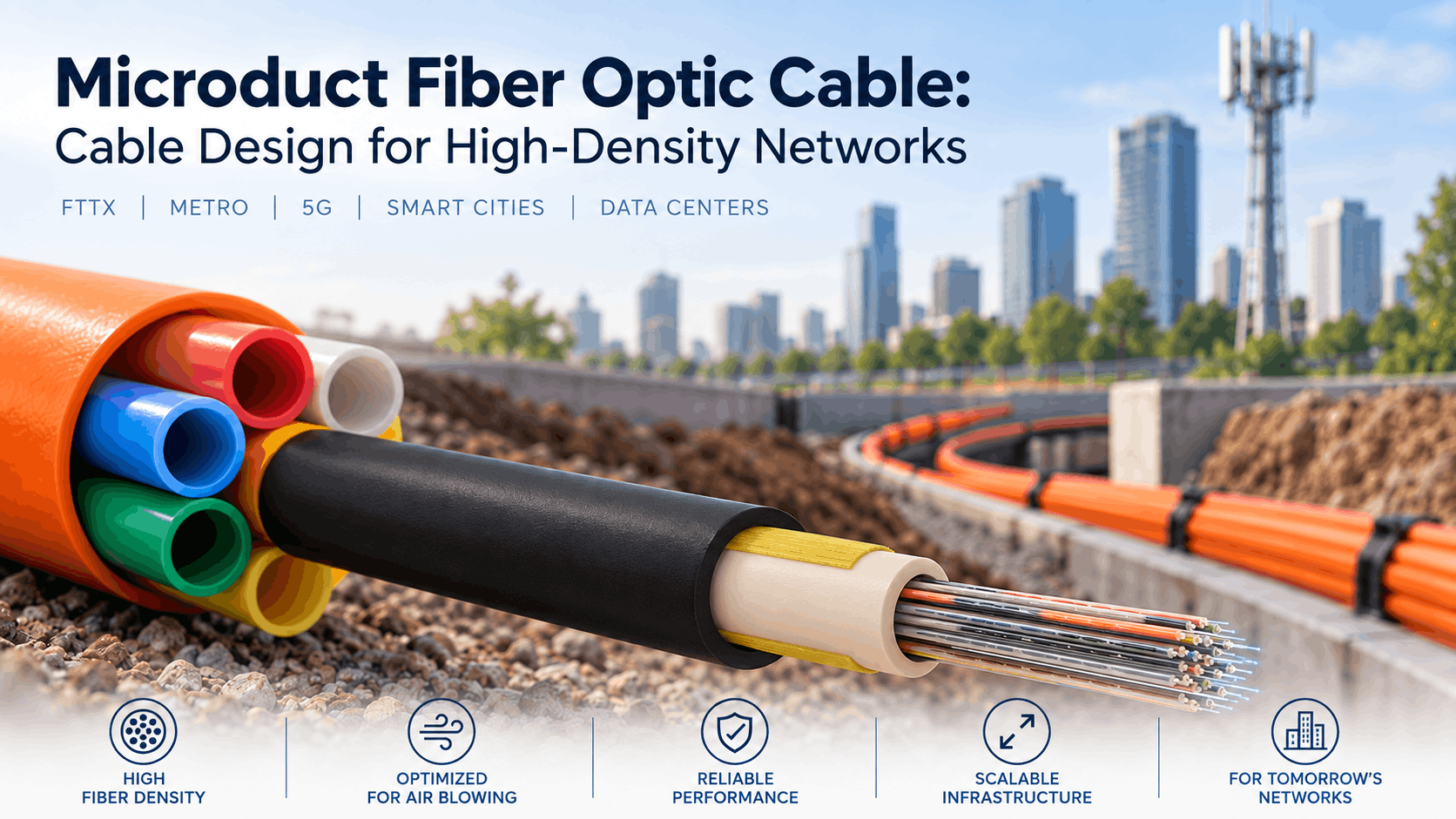
Microduct Fiber Optic Cable: Cable Design for High-Density Networks
Reading Time: 18 minutes
A microduct fiber optic cable is designed to place substantial optical capacity inside a small cable diameter while supporting efficient installation by air blowing through a microduct system. This combination makes microduct technology particularly attractive for FTTX, metropolitan networks, telecom backbones, 5G infrastructure, smart cities and other high-density fiber deployments.
However, a microduct cable should not be understood as a conventional duct cable that has simply been reduced in size. Diameter, cable weight, stiffness, sheath friction, tensile performance, water blocking and fiber organization all influence how effectively the cable travels through the microduct.
At the same time, the microduct itself forms part of the engineering system. Its internal diameter, route length, bends, surface condition and available airflow directly affect installation performance.
Therefore, successful microduct network design requires engineers to select the cable and duct together rather than treating them as independent products.
Quick answer: A microduct fiber optic cable uses a compact, lightweight construction optimized for blowing into small protective ducts. Low-count micro cables can use central loose-tube designs, while higher-count networks can use compact multi loose-tube constructions. The correct choice depends on fiber count, cable outside diameter, microduct internal diameter, blowing distance, route geometry, water blocking, mechanical requirements and future network-expansion strategy.
Microduct Fiber Optic Cable at a Glance
| Design Factor | Why It Matters |
|---|---|
| Small cable diameter | Allows higher fiber density within limited duct space |
| Low cable weight | Supports efficient air-blown installation |
| Optimized outer sheath | Helps reduce friction against the microduct |
| Fiber density | Increases network capacity without proportionally increasing pathway size |
| Central loose tube | Compact option for lower fiber counts |
| Multi loose tube | Scalable organization for higher fiber counts |
| Water blocking | Protects outdoor cable construction against longitudinal moisture migration |
| Microduct ID | Must be compatible with cable outside diameter |
| Route geometry | Bends and distance influence blowing performance |
| Mechanical performance | Cable must withstand installation without excessive fiber strain |
| Empty microduct capacity | Allows future cables to be installed when additional capacity is needed |
Consequently, microduct technology can increase both fiber density and long-term network flexibility when the complete system is engineered correctly.
What Is a Microduct Fiber Optic Cable?
A microduct fiber optic cable is a compact optical cable developed specifically for installation inside small-diameter ducts, normally using compressed-air blowing or jetting techniques.
Compared with a conventional duct cable, the design generally places greater emphasis on:
- Reduced outside diameter
- Low weight
- High fiber density
- Controlled stiffness
- Low-friction sheath characteristics
- Blowing performance
- Efficient use of duct capacity
Nevertheless, the cable still needs to protect the optical fibers against the mechanical and environmental loads expected during its service life.
Therefore, miniaturization cannot come at the expense of verified cable performance.
What Is a Microduct?
A microduct is a small protective pathway designed to receive a micro cable or fiber unit.
Several microducts can also be bundled together inside a larger protective structure.
As a result, one underground route can provide multiple independent pathways for present and future fiber capacity.
For example, a network operator can initially populate only some microducts while leaving others empty.
Later, additional cables can be installed as demand increases.
Consequently, the civil infrastructure can support incremental fiber expansion without reopening the complete route every time more capacity is required.
Why Microduct Networks Are Used for High-Density Fiber
Traditional network expansion often requires either installing larger cables initially or adding new cables later.
Microduct systems create another option.
Instead of committing all capacity on the first day, operators can install a network of small pathways and populate them progressively.
This approach can provide:
- Higher pathway utilization
- Incremental capacity growth
- Separation between cable groups
- Faster future upgrades
- Reduced need for repeated civil works
- Flexibility for different network owners or services
Therefore, microduct architecture can be especially valuable where the future fiber requirement remains difficult to predict.
Microduct Cable vs Conventional Duct Fiber Cable
Both cable types can be installed inside protective ducts, but their design priorities differ.
| Characteristic | Microduct Cable | Conventional Duct Cable |
|---|---|---|
| Outside diameter | Optimized to be compact | Generally larger |
| Fiber density | High | Depends on construction |
| Primary installation method | Air blowing / jetting | Pulling, blowing or jetting |
| Mechanical reliance on duct | Greater | Often more self-protective |
| Weight | Typically minimized | Can be higher |
| Expansion strategy | Populate additional microducts later | Often add another cable to main duct |
| Typical use | High-density access and backbone networks | General duct installations |
However, neither construction is inherently better.
A conventional duct cable can be ideal where substantial mechanical robustness is required and pathway space remains available. By contrast, microduct cable becomes particularly attractive where fiber density, duct utilization and future expansion matter more.
Micro Cable vs Microduct Fiber Unit
These terms should not automatically be treated as synonyms.
A microduct optical cable remains a cable with its own defined mechanical construction.
By contrast, a microduct fiber unit can rely even more heavily on the surrounding microduct for long-term mechanical protection.
Therefore, project engineers should determine whether the specification requires a:
- Microduct optical cable
- Microduct fiber unit
- Protected microduct system
This distinction becomes important when comparing mechanical performance, installation conditions and the level of protection provided outside the microduct.
Why Outside Diameter Is Critical
Outside diameter is one of the most important characteristics of a micro cable.
A smaller cable allows more optical capacity to fit within a restricted pathway.
Moreover, compact cables can make it possible to use smaller microducts or place more microducts inside an existing main duct.
However, minimizing diameter without considering mechanical behavior can create problems.
The cable must still maintain:
- Fiber protection
- Suitable crush resistance
- Tensile capability
- Temperature stability
- Water resistance
- Acceptable bending performance
Therefore, the correct objective is not the smallest possible cable. Instead, engineers should seek the smallest construction that reliably meets the required performance.
Microduct Fiber Optic Cable and Duct Sizing
The relationship between cable diameter and microduct internal diameter strongly affects installation.
If the cable is too large relative to the microduct, airflow becomes restricted and friction can increase.
On the other hand, an excessively large microduct around a very small cable may also reduce efficient aerodynamic interaction during blowing.
Consequently, cable-to-duct compatibility should follow manufacturer blowing recommendations rather than one universal fill-ratio assumption.
Important inputs include:
- Cable outside diameter
- Microduct internal diameter
- Cable stiffness
- Cable mass
- Sheath friction
- Blowing equipment
- Airflow
- Route geometry
Why Duct Fill Ratio Alone Is Not Enough
Traditional duct design often emphasizes percentage fill.
For blown micro cables, however, installation performance involves more than geometric area.
For example, two cables with the same outside diameter can behave differently because of:
- Different sheath surfaces
- Different stiffness
- Different mass
- Different push-force limits
- Different coefficients of friction
Therefore, buyers should not select the microduct solely from a cable-diameter chart without confirming the cable manufacturer’s recommended duct range.
Why Low Cable Weight Matters
Air-blown installation moves the cable using a combination of airflow and controlled mechanical feed.
As a result, lower mass can help reduce the force required to move the cable through long routes.
However, low weight is only one factor.
A very light cable with unsuitable stiffness or excessive surface friction may still perform poorly.
Consequently, successful blowing requires a balanced mechanical design rather than simply minimizing kilograms per kilometer.
The Role of Cable Stiffness
Stiffness affects how a cable responds to pushing force and route bends.
If a cable is too flexible, the pushing force applied at the blowing machine may not transfer efficiently along the cable.
Conversely, an excessively stiff construction can struggle through repeated curves and tight route geometry.
Therefore, microduct cable design aims for controlled stiffness that supports pushing while remaining suitable for the expected bending path.
Outer Sheath Design for Cable Blowing
The outer jacket forms the direct interface between the cable and the microduct.
Accordingly, sheath design can materially influence blowing performance.
Important characteristics can include:
- Low surface friction
- Abrasion resistance
- Controlled outer diameter
- Consistent roundness
- Environmental durability
HDPE is widely used for outdoor micro and duct cable jackets because suitable compounds combine mechanical durability with outdoor resistance.
Nevertheless, the finished surface and complete cable design matter more than the polymer name alone.
Coefficient of Friction in Microduct Installation
The coefficient of friction describes the interaction between the cable surface and the internal wall of the duct.
Lower friction can support longer and more predictable installation distances.
However, actual performance also depends on the specific pairing of cable and duct materials.
Therefore, friction should be evaluated as part of the cable-and-duct system.
In practice, cable construction, microduct type, installation method and route condition can all influence the effective friction encountered during deployment.
Microduct Fiber Optic Cable for Air-Blown Installation
During blowing, specialized equipment feeds the cable into the microduct while compressed air flows along the pathway.
The moving air helps distribute installation force along a greater portion of the cable length instead of relying exclusively on tensile pulling force from the far end.
As a result, suitable routes can support long installation distances while reducing excessive tensile stress on the optical fibers.
However, successful blowing depends heavily on:
- Microduct cleanliness
- Duct continuity
- Number of bends
- Bend radius
- Elevation changes
- Cable diameter
- Cable stiffness
- Air compressor capacity
- Blowing-machine settings
Consequently, cable performance cannot be predicted from outside diameter alone.
Installation Tension vs Push Force
Traditional pulling places substantial emphasis on maximum allowable tensile force.
Microduct blowing adds another important mechanical parameter: the force used to push the cable into the duct.
Too much pushing force can cause the cable to buckle or become mechanically overstressed.
Therefore, installers should observe the cable manufacturer’s approved installation tension and blowing-machine force limits.
In addition, the optical fibers must remain within the allowable strain limits throughout installation.
Route Geometry and Blowing Distance
A straight microduct route behaves very differently from a route containing many bends.
Each curve changes the way the cable contacts the duct wall.
Consequently, repeated bends can reduce achievable blowing distance.
Other route factors include:
- Vertical rises
- Vertical drops
- Microduct joints
- Internal surface contamination
- Temperature
- Existing deformation
Therefore, an advertised blowing distance should never be interpreted as a guaranteed value for every real installation.
Central Loose Tube Microduct Fiber Optic Cable
Lower and medium fiber counts can use a compact central loose-tube architecture.
In this design, all optical fibers are placed inside one PBT loose tube.
A typical construction can include:
- Optical fibers
- Thixotropic filling compound or dry water blocking
- PBT central loose tube
- Aramid or glass-yarn strength members
- Compact HDPE outer jacket
Because the architecture contains only one main optical tube, it can achieve a small outside diameter.
Therefore, central loose tube can be particularly efficient for lower-count microduct networks.
ETK Micro Central Loose Tube Design
ETK Kablo’s micro A-D(ZN)2Y construction provides a practical example of this architecture.
The published design uses one PBT loose tube, aramid-yarn non-metallic strength members and a UV-resistant HDPE outer sheath.
Available constructions include 2, 4, 6, 8, 12, 16, 20 and 24 optical fibers.
Moreover, the published cable outside diameter is only 3.8 mm for the 2–12 fiber versions and 4.8 mm for the 16–24 fiber versions.
As a result, substantial fiber capacity can be installed within a very small pathway.
Multi Loose Tube Microduct Fiber Optic Cable
As fiber count increases, multi loose-tube construction provides another approach.
Several compact PBT tubes can be stranded around a central FRP strength member.
Depending on design, the cable can also include:
- Water-swellable yarn
- Filler elements
- Ripcord
- Compact HDPE outer sheath
Consequently, the cable can organize a high number of fibers while maintaining a relatively small diameter.
High Fiber Count Without Proportionally Large Diameter
One of the main advantages of optimized microduct design is fiber density.
For example, ETK’s current A-DQ2Y microduct multi loose-tube family lists:
| Fiber Count | Published Cable Diameter |
|---|---|
| 12–72 fibers | 6.0 mm |
| 96 fibers | 7.2 mm |
| 120 fibers | 8.3 mm |
| 144 fibers | 8.3 or 8.6 mm depending on tube arrangement |
| 192 fibers | 9.8 mm |
| 288 fibers | 13.0 mm |
Therefore, fiber count can rise substantially without the same proportional increase in cable diameter.
Why Tube Arrangement Matters
Two high-count micro cables can contain the same number of fibers but organize them differently.
For example, a 144-fiber construction can use different fibers-per-tube and active-tube arrangements.
This can influence:
- Outside diameter
- Tube accessibility
- Mid-span access
- Fiber identification
- Splice organization
- Cable-core geometry
Therefore, buyers should request both the total fiber count and the actual loose-tube arrangement.
Microduct Fiber Optic Cable and Fiber Count
A microduct fiber optic cable can support both small access connections and high-capacity backbone networks.
Typical project counts can include:
- 12 fibers
- 24 fibers
- 48 fibers
- 72 fibers
- 96 fibers
- 144 fibers
- 192 fibers
- 288 fibers
However, fiber count should follow the network architecture rather than the maximum number that can physically fit inside the cable.
Consequently, engineers should balance present demand, spare fibers, future expansion and microduct capacity.
12 and 24 Fiber Microduct Cable
Lower-count micro cables can serve:
- Local FTTX branches
- Industrial connections
- Campus links
- Small access networks
- Telecom distribution
In these applications, a compact central loose-tube design can provide an attractive combination of fiber capacity and small diameter.
Furthermore, the reduced size can preserve more space inside the duct system for future cables.
48 to 96 Fiber Microduct Cable
Medium fiber counts can support aggregation and distribution roles.
Typical applications include:
- FTTX distribution
- Metro access
- Campus backbones
- Smart-city infrastructure
- 5G transport networks
- Utility communication systems
At this level, compact multi loose-tube construction can provide better fiber organization while maintaining efficient pathway use.
144 to 288 Fiber Microduct Cable
Higher-count micro cables become particularly useful where one corridor needs to carry substantial optical capacity.
For example, these cables can serve:
- Metropolitan backbones
- Dense FTTX feeder networks
- Telecom aggregation
- Regional broadband
- Large smart-city networks
- High-capacity utility infrastructure
However, route redundancy still matters.
A single 288-fiber cable provides high capacity, but all those fibers remain exposed to the same physical cable route.
Therefore, critical networks may still require geographically diverse pathways.
Fiber Type for Microduct Networks
Fiber count and cable dimensions do not determine the optical-fiber specification.
Depending on the product and project, suitable single-mode options can include:
- G.652.D
- G.657.A1
- G.657.A2
Meanwhile, specialized shorter-distance applications can use appropriate multimode fibers.
Nevertheless, high-density FTTX and metropolitan networks commonly favor single-mode fiber because of their distance and network architecture requirements.
G.652.D vs G.657 Fiber in Microduct Systems
G.652.D remains widely used for outdoor telecommunications and backbone applications.
By contrast, G.657.A1 and G.657.A2 provide improved macrobending performance.
That characteristic can become useful in access networks where cables and fibers pass through compact closures, cabinets or building-entry areas.
Therefore, engineers should select the optical fiber according to the complete network route rather than the microduct alone.
Microduct Fiber Optic Cable and Water Blocking
Outdoor micro cables still require protection against longitudinal moisture migration.
Depending on the construction, water blocking can use:
- Thixotropic gel inside loose tubes
- Water-swellable yarn
- Water-swellable tape
- Dry water-blocking elements
- Combinations of these technologies
For example, a multi loose-tube design can use gel-filled tubes together with water-swellable yarn in the surrounding cable core.
Consequently, a compact micro cable can still provide robust moisture protection.
Dry vs Gel-Filled Microduct Cable
Both water-blocking approaches are possible.
Gel-filled loose tubes provide an established outdoor protection system.
Meanwhile, dry water-blocking elements can simplify cable preparation and reduce gel handling.
However, the words “dry core” and “gel-free” should not automatically be treated as identical.
A cable can contain gel-filled tubes while using dry water blocking around those tubes.
Therefore, buyers should examine the complete construction table when specifying water-blocking technology.
Does a Micro Cable Need Armour?
Normally, the microduct itself provides an important level of physical protection.
As a result, many microduct cables use non-metallic compact constructions rather than heavy metallic armour.
However, the complete infrastructure still needs to protect the microduct system against:
- Crushing
- Excavation damage
- Rodents
- Water
- Ground movement
- Industrial mechanical exposure
Therefore, mechanical protection can be provided at the microduct or protected-duct level rather than by adding heavy armour directly to every micro cable.
Microduct Cable vs Direct Burial Fiber Cable
A microduct fiber cable should not automatically be treated as a direct-burial cable.
The cable relies on the surrounding pathway for part of its mechanical protection.
By contrast, a dedicated direct-burial fiber cable can include:
- Corrugated steel tape
- Steel Wire Armour
- Non-metallic reinforcement
- Heavy outer sheath
- Additional water protection
Therefore, if a microduct network is directly buried, the protected microduct system itself must be designed for that environment.
Microduct Fiber Optic Cable for FTTX Networks
FTTX is one of the strongest applications for microduct technology.
Subscriber numbers can increase gradually over many years.
Therefore, installing every future fiber cable during the first phase can create unnecessary initial cost.
Instead, operators can install microduct capacity and add cables as demand develops.
As a result, the network can expand from:
- Feeder routes
- Distribution areas
- Street cabinets
- MDU connections
- Business services
without repeatedly rebuilding the entire underground pathway.
Microduct Fiber Optic Cable for Metro Networks
Metropolitan networks require high fiber density within constrained urban corridors.
Existing duct capacity can be extremely valuable because additional civil works are disruptive and expensive.
Consequently, microduct systems can help operators divide available pathway space into multiple smaller, independently usable routes.
Moreover, high-count micro cables can provide substantial backbone capacity without consuming the diameter of traditional large cables.
5G and Mobile Backhaul Applications
Mobile networks require fiber connectivity between aggregation sites, base stations and core infrastructure.
As network density increases, additional fiber routes may be needed over time.
Therefore, microduct architecture can provide useful expansion flexibility for:
- 5G transport
- Small-cell networks
- Mobile fronthaul
- Backhaul
- Edge infrastructure
However, exact fiber counts and redundancy should follow the operator’s network architecture.
Microduct Fiber Optic Cable for Smart Cities
Smart-city networks combine many different communications requirements across one urban area.
Potential connections include:
- Traffic systems
- CCTV
- Public Wi-Fi
- 5G infrastructure
- IoT gateways
- Utility monitoring
- Municipal buildings
Because these services can expand independently, reserving separate microduct pathways can provide useful operational flexibility.
Consequently, the city can add optical capacity without replacing the entire backbone each time a new service appears.
Microduct Cable for Data Center Campus Networks
Large data-center campuses can require substantial fiber capacity between buildings.
In addition, network capacity can grow rapidly as new halls or facilities are commissioned.
Therefore, microduct systems can provide an expandable underground pathway between buildings.
However, cable fire performance must also be considered where an outdoor cable enters an occupied or regulated indoor environment.
Accordingly, indoor transition rules and the appropriate cable construction should be included in the design.
Microduct Networks for Railway Infrastructure
Railway corridors provide natural long-distance pathways for communication systems.
Fiber demand can include:
- Signaling communications
- CCTV
- Passenger information
- Telecommunications
- Station networks
- Operational data
A microduct system can allow additional fiber cables to be introduced later as railway systems expand.
Nevertheless, the protected duct infrastructure must withstand the mechanical and environmental conditions of the railway route.
Microduct Systems for Utility Networks
Electricity, water, gas and other utilities increasingly depend on fiber for monitoring and control.
Because utility networks frequently evolve over long service periods, spare pathway capacity can be valuable.
For example, empty microducts can support later additions for:
- SCADA
- Protection systems
- Smart metering
- Substation communications
- Operational networks
Therefore, microduct architecture can support both present communication requirements and future digitalization.
IEC 60794-5 and Microduct Cabling
IEC 60794-5 provides the sectional specification framework for microduct optical fiber cabling designed for installation by blowing.
The framework covers:
- Microduct optical fiber cables
- Microduct fiber units
- Microducts
- Protected microducts
Importantly, the standard treats these elements as parts of a coordinated microduct cabling system.
Therefore, compliance should not be interpreted only as a property of the optical cable itself.
IEC 60794-5-10 for Outdoor Microduct Cables
IEC 60794-5-10 addresses outdoor microduct optical fiber cables and their associated microduct systems for installation by blowing.
Consequently, it provides a useful family-specification reference for outdoor micro cable projects.
Nevertheless, individual project requirements still need to define fiber count, dimensions, environmental conditions and mechanical performance.
Microduct Fiber Units and IEC 60794-5-20
Microduct fiber units are covered separately because they can provide less independent mechanical protection than a complete microduct optical cable.
Instead, they rely more heavily on the surrounding microduct or protected housing.
Therefore, engineers should avoid specifying a fiber unit as though it were automatically equivalent to a more robust micro cable.
Mechanical Tests for Microduct Cable
A compact cable still needs verified mechanical performance.
Depending on the product specification, relevant tests can include:
- Tensile performance
- Crush resistance
- Impact resistance
- Torsion
- Repeated bending
- Bending
- Temperature cycling
- Water penetration
As a result, buyers should evaluate actual specified test values rather than assume that every small-diameter cable provides equivalent performance.
Why Maximum Installation Tension Matters
Although air blowing reduces reliance on end pulling, the cable still experiences mechanical forces during deployment.
Excessive tension can create fiber strain or permanently damage the cable structure.
Therefore, the approved maximum installation tension should remain part of the installation procedure.
For example, ETK’s compact microSLT A-D(ZN)2Y product publishes a maximum installation tension of 650 N for its standard range.
Crush Resistance and Microduct Protection
Micro cables are compact, but compact does not mean mechanically untested.
Nevertheless, the protective microduct forms an important external defense against direct mechanical loading.
Therefore, the complete route should be evaluated at two levels:
- Cable mechanical performance inside the duct
- Microduct or protected-duct resistance to the surrounding environment
This system approach is particularly important for buried infrastructure.
Bending Radius
Micro cable size can make routing easier, but every cable still has a minimum permitted bending radius.
Excessive bending can create:
- Optical attenuation
- Fiber strain
- Tube deformation
- Permanent cable damage
Consequently, route design should consider both cable bending radius and microduct bend geometry before installation begins.
Temperature Performance
Outdoor microduct networks can experience wide seasonal temperature changes.
Therefore, engineers should check:
- Storage temperature
- Transport temperature
- Installation temperature
- Operating temperature
In addition, the cable and microduct can have different thermal-expansion characteristics.
Accordingly, the complete system should be designed for the expected environment.
Does a Smaller Cable Always Blow Farther?
No.
Smaller diameter can reduce weight and improve pathway utilization, but blowing performance also depends on:
- Cable stiffness
- Friction
- Duct diameter
- Airflow
- Route bends
- Push force
- Temperature
Therefore, a smaller cable should not automatically be assumed to achieve a longer installation distance.
Does Higher Fiber Density Make the Cable Less Reliable?
Not when the cable is properly engineered and tested.
Modern loose-tube designs can organize substantial fiber counts within compact dimensions while maintaining the required optical and mechanical performance.
However, design margins become increasingly important as construction density rises.
Consequently, high-density cable should be evaluated through verified tensile, crush, temperature and water tests rather than judged from dimensions alone.
Microduct Fiber Optic Cable vs Microfiber Cable Terminology
Different markets use terms such as:
- Microduct cable
- Micro fiber cable
- Micro cable
- Air-blown fiber cable
- Blown fiber cable
However, these terms are not always technically interchangeable.
For procurement, the safest approach is to define the actual construction, fiber count, cable diameter, duct size and applicable standards.
Common Mistakes When Selecting Microduct Fiber Optic Cable
1. Choosing the Cable Before Choosing the Microduct
The cable and pathway should be engineered as one system.
2. Selecting Only by Outside Diameter
Weight, stiffness, friction and mechanical performance also affect installation.
3. Assuming the Smallest Cable Is Always Best
The cable still needs adequate mechanical and environmental protection.
4. Using One Universal Cable-to-Duct Ratio
Blowing performance depends on more than geometric fill.
5. Ignoring Route Bends
Repeated curves can significantly reduce achievable blowing distance.
6. Ignoring Push Force
Excessive pushing can buckle or damage the cable.
7. Ignoring Cable Surface Friction
The outer jacket directly interacts with the microduct during installation.
8. Treating Microduct Cable as Direct-Burial Cable
The surrounding duct system provides important external protection.
9. Confusing a Micro Cable with a Microduct Fiber Unit
The two can provide different levels of independent mechanical protection.
10. Choosing Fiber Count Only for Current Demand
Future network growth should also influence the selected capacity.
11. Filling Every Microduct on Day One
Leaving spare pathways can preserve one of the main strategic advantages of microduct infrastructure.
12. Ignoring Water Blocking
Outdoor micro cables still require a suitable moisture-protection system.
13. Assuming Dry Core Means Completely Gel-Free
Some constructions use gel-filled tubes together with dry cable-core blocking.
14. Ignoring Tube Arrangement
High-count cables can organize the same fiber count in different ways.
15. Ignoring Bending Radius
Compact size does not eliminate minimum bend requirements.
16. Ignoring Mechanical Test Values
The complete cable should meet defined installation and operating requirements.
17. Assuming One Blowing Distance Applies to Every Route
Actual distance depends strongly on route and installation conditions.
18. Forgetting Future Network Ownership
Separate empty microducts can provide useful capacity for new operators, services or technologies.
How to Select a Microduct Fiber Optic Cable
A practical selection process should begin with the network requirement and work outward toward the pathway.
1. Determine the Required Fiber Count
Calculate active fibers, spare capacity and expected growth.
2. Select the Fiber Type
Choose G.652.D, G.657 or another appropriate optical specification according to the network design.
3. Choose Central or Multi Loose Tube
Lower counts can favor compact central-tube designs, while high counts can benefit from multi-tube organization.
4. Identify the Required Cable Diameter
Compare fiber capacity with available microduct space.
5. Select the Compatible Microduct
Use the cable manufacturer’s recommended cable-to-duct combination.
6. Review the Planned Blowing Route
Consider length, bends, elevation and joint locations.
7. Check Mechanical Limits
Verify installation tension, push-force guidance, bending radius and crush performance.
8. Define Water Blocking
Select gel-filled, dry or hybrid construction according to project requirements.
9. Review Environmental Conditions
Confirm temperature, UV and outdoor requirements.
10. Preserve Future Microduct Capacity
Decide how many pathways should remain empty for future expansion.
What Should Buyers Include in a Microduct Cable RFQ?
An RFQ requesting only “microduct fiber cable” leaves several important parameters unresolved.
A strong technical specification should include:
- Fiber count
- Fiber type
- G.652.D / G.657.A1 / G.657.A2 where required
- Central loose tube or multi loose tube
- Fibers per tube
- Tube count
- Maximum cable outside diameter
- Target microduct internal diameter
- Target microduct external diameter where relevant
- Expected blowing distance
- Route bend information
- Cable weight
- Outer sheath material
- Low-friction requirement
- Water-blocking technology
- Maximum installation tension
- Maximum operating tension
- Push-force requirement where specified
- Crush resistance
- Impact resistance
- Minimum bending radius
- Operating temperature
- Installation temperature
- Water-penetration performance
- Applicable IEC 60794 requirements
- Fiber identification system
- Tube identification system
- Cable marking
- Drum length
- Optical test report
- Mechanical test documentation
As a result, the manufacturer can evaluate cable geometry and blowing performance against the actual pathway rather than quoting a generic small-diameter cable.
ETK Kablo Microduct Fiber Optic Cable Solutions
ETK Kablo manufactures microduct fiber optic cable constructions for FTTX, metropolitan, telecom, broadband, smart-city, campus and other high-density optical networks.
For lower fiber counts, the microSLT A-D(ZN)2Y family provides a compact non-metallic central loose-tube construction with aramid-yarn strength members and an HDPE outer jacket.
The standard published range covers 2 to 24 fibers with cable diameters from approximately 3.8 to 4.8 mm, depending on fiber count.
Meanwhile, the A-DQ2Y mdMLT family uses a compact multi loose-tube architecture with a non-metallic FRP central strength member, water-swellable yarn and an HDPE outer jacket.
That product family scales from 12 fibers through 288 fibers while maintaining compact dimensions for high-density duct infrastructure.
For example, ETK publishes a 72-fiber version at approximately 6.0 mm diameter, a 144-fiber design at approximately 8.3–8.6 mm depending on tube arrangement, and a 288-fiber construction at approximately 13.0 mm.
Therefore, network designers can select fiber capacity according to the actual access, distribution or backbone requirement while maintaining efficient use of microduct space.
Frequently Asked Questions
What is a microduct fiber optic cable?
It is a compact optical cable optimized for installation by blowing inside a small protective microduct.
What is the difference between micro cable and normal fiber cable?
Micro cable places greater emphasis on small diameter, low weight, controlled stiffness and blowing performance, while conventional cable may provide a larger and more mechanically self-contained construction.
How is microduct fiber cable installed?
It is commonly installed using specialized equipment that mechanically feeds the cable while compressed air flows through the microduct.
Can microduct cable be pulled?
Some constructions may permit suitable short pulling operations, but the intended installation method and force limits should follow the specific manufacturer datasheet.
Can microduct cable be directly buried?
The micro cable itself should not automatically be considered a direct-burial cable. A protected microduct system designed for direct burial can provide the necessary external protection.
What fiber counts are available in microduct cable?
Microduct constructions can range from low fiber counts to high-capacity designs such as 96, 144, 192 and 288 fibers, depending on the manufacturer and cable architecture.
Can 288 fiber cable fit in a microduct system?
Yes. High-density multi loose-tube micro cables can support 288 fibers, provided the selected microduct internal diameter is compatible with the cable outside diameter and blowing requirements.
What is a microduct fiber unit?
A microduct fiber unit is a lightweight optical-fiber element that relies more heavily on the surrounding microduct for mechanical protection than a complete microduct optical cable.
Which IEC standard covers microduct cables?
IEC 60794-5 provides the sectional specification for microduct cabling designed for installation by blowing, while IEC 60794-5-10 addresses outdoor microduct optical cable systems.
What is IEC 60794-5-20?
IEC 60794-5-20 covers outdoor microduct fiber units and associated microduct or protected-microduct systems.
Why is microduct cable so small?
The construction is optimized to increase fiber density and reduce weight while relying on the microduct system for additional environmental and mechanical protection.
Does smaller diameter mean longer blowing distance?
Not automatically. Cable friction, stiffness, weight, duct size, route geometry, airflow and push force also influence installation distance.
What is the best cable-to-microduct ratio?
There is no single ratio that suits every cable and installation. The cable manufacturer’s recommended microduct size and blowing guidance should govern.
Why is HDPE used for micro cables?
Suitable HDPE compounds provide outdoor durability, abrasion resistance and useful surface characteristics for duct installation.
Can microduct cable be dry core?
Yes. Micro cables can use dry water-blocking materials, gel-filled loose tubes or combinations of both technologies.
Can microduct cable use G.657.A2 fiber?
Suitable microduct constructions can use bend-insensitive G.657 fiber where the project requires it, although the specific product datasheet should confirm available fiber types.
Is microduct cable armored?
Many microduct cables use compact non-metallic constructions because the surrounding microduct supplies important external protection. Heavy armour is not automatically required.
Is microduct cable suitable for FTTX?
Yes. FTTX is a major application because microduct systems allow operators to add fiber capacity progressively as subscriber demand develops.
Is microduct cable suitable for metro backbones?
Yes. High-count compact cables can provide substantial fiber density within restricted urban duct space.
What affects fiber cable blowing distance?
Important factors include cable diameter, weight, stiffness, sheath friction, microduct size, airflow, bends, route length, elevation and blowing-machine settings.
Which microduct fiber optic cable should I choose?
Select the required fiber count first, then evaluate cable diameter, microduct size, route geometry, blowing requirements, water blocking, mechanical performance and future expansion capacity.
Conclusion
A microduct fiber optic cable is designed around one central objective: placing substantial optical capacity into a compact pathway while allowing efficient installation and future network expansion.
Small outside diameter is important, but it represents only one part of the engineering problem. Cable mass, stiffness, sheath friction, tensile capability and bending behavior also influence blowing performance.
Meanwhile, the microduct plays an equally important role. Its internal diameter, bends, condition and airflow characteristics affect how efficiently the cable can be installed.
Therefore, the cable and microduct should always be treated as one coordinated system.
Central loose-tube micro cables can provide highly compact constructions for lower fiber counts. By contrast, multi loose-tube micro cables can organize 96, 144, 192, 288 and other high-count configurations while maintaining high fiber density.
Water blocking, fiber type and mechanical performance remain separate specification decisions. Likewise, a micro cable should not automatically be treated as directly buried simply because it is designed for outdoor telecommunications.
For FTTX and metropolitan networks, one of the greatest advantages comes from scalability. Operators can install multiple microducts initially, populate only the capacity they require today and blow additional cables into the remaining pathways when demand develops.
As a result, microduct infrastructure can extend the useful life of underground civil works and provide a flexible path toward higher network density.
For engineering and purchasing teams, the best approach is therefore to determine fiber count first, identify the required cable diameter second, select the compatible microduct third and then verify blowing, mechanical, water-blocking and environmental performance for the complete route.
The best microduct design is not simply the smallest cable available. It is the cable-and-duct combination that provides the required optical capacity, installs reliably and leaves enough flexibility for the network to grow.
Benzer yazılar

12/24/48/96/144/288 Core Fiber Optic Cable: Selection Guide
A fiber optic cable core count determines how many individual optical fibers are available inside one cable for active connections, red...
Central Loose Tube vs Multi Loose Tube Fiber Optic Cable: Which Should You Choose?
Choosing between central loose tube vs multi loose tube fiber optic cable starts with the internal cable architecture. Both constructio...
Micro-Module Fiber Cable: High-Density Design & Selection Guide
A micro module fiber cable groups optical fibers inside thin, flexible modules rather than conventional rigid buffer tubes. This archit...
SWA Fiber Optic Cable: Construction, Applications & Selection Guide
SWA fiber optic cable combines optical fibers with a Steel Wire Armour layer that provides additional mechanical reinforcement around t...

What Is a Fiber Optic Cable? Types, Structure & Selection Guide
A fiber optic cable carries information as light through one or more optical fibers. Instead of transmitting electrical signals through...
Fiber Optic Cable Types: Complete Selection Guide
Fiber optic cable types differ according to optical fiber, cable construction, installation environment, mechanical protection, water b...


