





 President’s Message
Blog
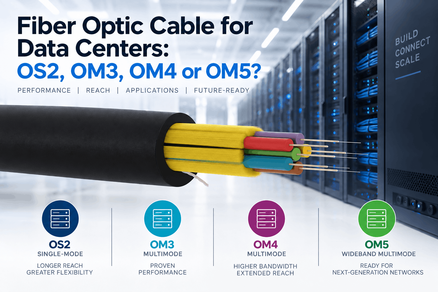
Fiber Optic Cable for Data Centers: OS2, OM3, OM4 or OM5?
Reading Time: 18 minutes
Selecting the right data center fiber cable requires more than choosing between single-mode and multimode fiber. Modern data centers can contain short switch-to-switch links inside one room, high-density leaf-spine connections, building-to-building backbones and campus links extending hundreds of meters or several kilometers.
Therefore, OS2, OM3, OM4 and OM5 should not be treated as simple performance levels where a higher designation is automatically better. Each fiber type serves a different combination of transmission distance, optical transceiver technology, connector architecture and network economics.
OS2 is single-mode fiber and provides the greatest distance flexibility. Meanwhile, OM3, OM4 and OM5 are laser-optimized 50/125 µm multimode fibers designed primarily for shorter optical links. OM4 offers significantly greater modal bandwidth than OM3, while OM5 extends wideband multimode performance across additional wavelengths for compatible multi-wavelength transceivers.
However, the optical transceiver ultimately determines how the fiber will be used. Two links using the same OM4 cable can support very different speeds and distances because their transceivers use different modulation, lane counts, wavelengths and optical budgets.
Quick answer: OM3 remains suitable for many existing short-reach installations. OM4 is generally the stronger multimode choice for new high-speed data center networks. OM5 should be selected when the planned multi-wavelength multimode optics can genuinely use its wider wavelength specification. OS2 becomes especially attractive for longer links, campus connections, high-speed migration and projects seeking maximum flexibility across future single-mode transceiver generations.
OS2, OM3, OM4 and OM5 at a Glance
| Characteristic | OS2 | OM3 | OM4 | OM5 |
|---|---|---|---|---|
| Fiber family | Single-mode | Multimode | Multimode | Wideband multimode |
| Typical core diameter | Approximately 9 µm | 50 µm | 50 µm | 50 µm |
| Important operating wavelengths | Commonly 1310 / 1550 nm | Primarily 850 nm | Primarily 850 nm | 850–953 nm wideband specification |
| 850 nm effective modal bandwidth | Not applicable | 2000 MHz·km | 4700 MHz·km | 4700 MHz·km |
| Primary data center position | Short to very long links | Short-reach multimode | Higher-performance short-reach multimode | Multi-wavelength multimode applications |
| Typical connector architecture | LC duplex or MPO | LC duplex or MPO | LC duplex or MPO | LC duplex or MPO |
| Main advantage | Distance and technology flexibility | Established multimode infrastructure | Strong multimode bandwidth and reach | Wideband multimode capability |
| Main selection caution | Transceiver economics | Lower reach than OM4 at many high-speed interfaces | Still limited compared with single-mode reach | Benefit depends strongly on transceiver technology |
Most importantly, these characteristics describe the optical medium. They do not define the complete cable construction, connector system or supported Ethernet speed by themselves.
What Is OS2 Fiber?
OS2 is a single-mode optical fiber cabling category intended for low-attenuation transmission over significantly greater distances than multimode fiber.
Its small optical core allows essentially one propagation mode to travel through the fiber. As a result, OS2 avoids the modal dispersion that limits multimode transmission distance.
In data center environments, single-mode constructions can use suitable fibers such as:
- G.652.D
- G.657.A1
- G.657.A2
The exact fiber should follow the cable design and project specification.
Moreover, bend-insensitive G.657 variants can provide useful advantages where routing passes through compact trays, cabinets, equipment areas or building-entry locations.
Where Is OS2 Used in Data Centers?
OS2 can serve much more than long-distance telecommunications.
Modern data centers can use single-mode fiber for:
- Spine-to-leaf connections
- Switch-to-switch links
- Meet-me rooms
- Campus backbones
- Data center interconnects
- Building-to-building connections
- Cloud infrastructure
- AI and high-performance computing networks
Historically, multimode optics often provided a compelling cost advantage for short links. However, the economics of high-speed single-mode optics continue to evolve.
Therefore, engineers should compare the complete link cost rather than assuming that OS2 must always be reserved for long-distance connections.
What Is OM3 Multimode Fiber?
OM3 is a laser-optimized 50/125 µm multimode fiber designed for high-speed transmission using short-wavelength optical sources.
Its specified effective modal bandwidth at 850 nm is 2000 MHz·km.
OM3 became widely deployed as data centers migrated from traditional Gigabit Ethernet toward 10G and higher-speed multimode networks.
As a result, substantial installed OM3 infrastructure remains operational today.
Typical uses can include:
- Short server-room links
- Legacy structured cabling
- Short switch connections
- Enterprise data centers
- Existing 10G and higher-speed channels within supported reach
Is OM3 Still Suitable for New Data Centers?
Yes, but the answer depends on the network roadmap.
If the project has short links, defined transceiver requirements and limited future speed migration, OM3 can still satisfy the technical requirement.
However, OM4 provides greater modal bandwidth and generally supports longer reach for many high-speed multimode interfaces.
Consequently, the incremental cable-material saving from choosing OM3 should be compared with the expected lifetime of the structured cabling system.
For a new greenfield facility designed to support several generations of network upgrades, OM4 or OS2 may provide greater flexibility.
What Is OM4 Multimode Fiber?
OM4 is also a laser-optimized 50/125 µm multimode fiber, but it provides substantially greater effective modal bandwidth than OM3.
At 850 nm:
- OM3 minimum EMB: 2000 MHz·km
- OM4 minimum EMB: 4700 MHz·km
That improved bandwidth can translate into greater supported distance for many short-reach Ethernet and Fibre Channel interfaces.
Therefore, OM4 has become a particularly important multimode option for modern data centers.
Why OM4 Is Often the Multimode Reference Point
OM4 offers a useful balance between performance, installed ecosystem and transceiver availability.
It works with standard short-wavelength multimode optics while providing more performance margin than OM3.
In addition, the majority of data center multimode links are relatively short. For these environments, multimode transceivers can still provide attractive technical and economic characteristics.
Consequently, an engineer who has already decided to use multimode fiber will often compare other choices against OM4 first.
What Is OM5 Multimode Fiber?
OM5 is a 50/125 µm wideband multimode fiber.
It meets the OM4 bandwidth requirement at 850 nm while also providing defined bandwidth performance at longer short wavelengths.
In particular, OM5 supports a wideband specification extending through approximately 953 nm.
This allows compatible optical systems to transmit several wavelengths across one multimode fiber.
Therefore, OM5 was developed to support technologies such as short-wavelength wavelength-division multiplexing rather than simply to replace OM4 in every data center link.
OM4 vs OM5: Is OM5 Automatically Better?
No.
This is one of the most important points when selecting a data center fiber cable.
For conventional single-wavelength multimode transceivers operating around 850 nm, OM5 does not automatically provide greater reach than OM4 because both meet the same minimum 850 nm effective modal bandwidth requirement.
By contrast, compatible multi-wavelength optics can benefit from OM5 because the fiber has specified wideband performance beyond 850 nm.
Therefore:
Single-wavelength 850 nm optics → OM5 may provide no meaningful reach advantage over OM4.
Compatible multi-wavelength multimode optics → OM5 can provide additional value.
Why the Transceiver Matters More Than the Fiber Name
A fiber category cannot independently determine Ethernet reach.
The transceiver defines important characteristics such as:
- Operating wavelength
- Number of optical lanes
- Modulation format
- Transmitter power
- Receiver sensitivity
- Permitted channel loss
- Required fiber type
For example, two 400G multimode transceivers can support different maximum distances over the same OM4 fiber because they use different optical architectures.
Likewise, one OM5-compatible multi-wavelength transceiver can gain additional reach from OM5 while another 850 nm transceiver gains nothing compared with OM4.
Consequently, the correct sequence is:
Choose the network interface and required reach first. Then select the fiber category that supports it.
Representative 400G Fiber Examples
Modern 400G optics demonstrate why fiber selection cannot rely on a simple “OM3 vs OM4 vs OM5” ranking.
For example, current transceiver families can include:
| 400G Optical Approach | Fiber | Representative Reach Pattern |
|---|---|---|
| Parallel 850 nm multimode | OM3 / OM4 | Short reach, with OM4 generally supporting greater distance |
| Multi-wavelength multimode | OM3 / OM4 / OM5 | OM5 can provide additional reach where longer wavelengths are used |
| DR-class single-mode | Single-mode | Hundreds of meters |
| FR-class single-mode | Single-mode | Kilometer-scale links |
| LR-class single-mode | Single-mode | Longer campus and interconnect links |
Therefore, buyers should never approve a fiber specification without also reviewing the planned optical modules.
Data Center Fiber Cable for 400G and 800G Networks
As data centers migrate toward 400G and 800G, cabling decisions become increasingly dependent on the long-term transceiver roadmap.
Higher data rates can use several architectures, including:
- Parallel multimode optics
- Duplex multimode BiDi optics
- Single-mode parallel optics
- Single-mode wavelength-division multiplexing
- Breakout architectures
Moreover, the optical interface used at one network generation may not resemble the interface selected at the next.
For this reason, long-lived structured cabling should be selected with migration flexibility in mind.
OS2 can offer particularly broad reach flexibility. Meanwhile, OM4 remains highly relevant for defined short-reach multimode architectures.
What About AI and High-Density Computing Clusters?
AI and high-performance computing environments place intense bandwidth demands between switches, accelerators, storage and compute infrastructure.
However, not every connection uses permanent structured fiber cabling.
Depending on reach and architecture, an AI cluster can use:
- Direct-attach copper
- Active electrical cables
- Active optical cables
- Multimode structured fiber
- Single-mode structured fiber
Therefore, the permanent cable infrastructure should be planned around the physical topology rather than around the headline server speed alone.
For long-lived backbone pathways, fiber count, connector density and migration strategy can matter as much as the fiber category itself.
Data Center Fiber Cable: OS2 vs OM4
This is one of the most useful comparisons for a greenfield facility.
| Decision Factor | OS2 | OM4 |
|---|---|---|
| Distance flexibility | Very high | Optimized for short reach |
| Short-reach transceiver ecosystem | Strong and expanding | Very strong |
| Typical optical source | Single-mode laser technology | 850 nm VCSEL |
| Campus / interbuilding | Excellent | Distance-dependent |
| High-speed migration | Very flexible | Depends on future multimode interface |
| Short-link economics | Depends on optics | Often attractive |
| Parallel optics | Available | Available |
| Duplex optics | Available | Available |
In practice, there is no universal winner.
If the data center has predictable short channels and a strong multimode transceiver strategy, OM4 can remain highly effective.
However, where the facility includes longer runs, multiple buildings or an uncertain long-term transceiver roadmap, OS2 can provide additional flexibility.
Data Center Fiber Cable: OM3 vs OM4
Both fibers use a 50 µm multimode core and support laser-optimized transmission.
The key difference is modal bandwidth.
Because OM4 provides more than twice the specified effective modal bandwidth of OM3 at 850 nm, many high-speed interfaces support greater distance over OM4.
Therefore, new installations should compare:
- Required maximum link length
- Current Ethernet speed
- Next migration speed
- Existing installed fiber
- Transceiver availability
- Incremental cable cost
An existing OM3 plant does not necessarily need replacement if it supports the required channel. Nevertheless, a new long-life installation may justify OM4.
Data Center Fiber Cable: OM4 vs OM5
OM5 retains OM4-level bandwidth at 850 nm and adds controlled performance at longer wavelengths.
As a result, OM5 can support wideband multimode systems more predictably.
However, that additional capability only creates value when the optical module actually uses it.
Therefore, before paying a premium for OM5, the design team should ask:
- Will the transceiver use multiple short wavelengths?
- Does the selected manufacturer specify additional reach over OM5?
- Will future network generations use the same wideband architecture?
- Does the project require OM5 for standardization?
If the answers are no, OM4 may provide the same usable performance for the intended interface.
When Should You Choose OM5?
OM5 becomes most logical when there is a deliberate multi-wavelength multimode strategy.
For example, a network using compatible BiDi or SWDM-type optical architectures may be able to use the additional wideband specification.
In addition, OM5 can make sense where a customer has standardized globally on wideband multimode infrastructure.
However, OM5 should not be selected merely because the number “5” is higher than “4.”
Its value must come from the optical system.
When Should You Choose OS2?
OS2 becomes particularly attractive when the network requires:
- Longer transmission distances
- Interbuilding connections
- Campus backbones
- Data center interconnects
- Greater transceiver migration flexibility
- High-speed links beyond practical multimode reach
Furthermore, one single-mode cable plant can support a broad range of optical technologies across different distances.
Therefore, OS2 can reduce the need to change the permanent cable merely because the network speed increases.
When Is OM4 the Better Choice?
OM4 can be particularly effective when links remain within the supported reach of the selected short-reach multimode transceiver.
For example, it can suit:
- Equipment-room connections
- Row-to-row links
- Short spine-leaf channels
- Enterprise data centers
- Short campus-building links where reach permits
Meanwhile, multimode VCSEL-based optics can provide attractive cost and power characteristics for appropriate short-distance interfaces.
Consequently, OS2 should not automatically replace OM4 simply because single-mode can transmit farther.
Data Center Fiber Cable for Spine-Leaf Networks
Leaf-spine architecture creates large numbers of high-speed east-west connections.
Therefore, physical distance between leaf and spine switches becomes a major cabling input.
A compact facility can keep most links well within multimode range.
By contrast, a distributed campus architecture may place spine switches, meet-me rooms or network areas much farther apart.
As a result, one data center can legitimately use:
- OM4 for shorter internal channels
- OS2 for longer backbone paths
- Both fiber families in different parts of the same facility
Duplex Fiber vs Parallel Fiber
Fiber type and fiber count are separate decisions.
Some optical interfaces use one transmit fiber and one receive fiber.
These duplex connections commonly use two fibers per link.
By contrast, parallel optical interfaces divide the signal across several fibers in each direction.
Therefore, a 100G or 400G link can consume different numbers of physical fibers depending on the selected transceiver.
LC Duplex Connectivity
LC duplex connectors remain widely used for two-fiber optical channels.
They can support both multimode and single-mode systems when the connectors and optics match the fiber type.
Duplex architecture can simplify fiber utilization because each connection consumes only two fibers.
Moreover, BiDi and wavelength-multiplexed technologies can transport increasingly high data rates through duplex connectivity.
Therefore, connector architecture should form part of the migration strategy.
MPO Connectivity and Parallel Optics
MPO connectors allow several optical fibers to terminate in one compact interface.
As a result, they are widely associated with high-density trunk cabling and parallel optical transmission.
Depending on the application, MPO-based systems can support:
- Multimode parallel optics
- Single-mode parallel optics
- Breakout connections
- High-density trunk systems
However, the number of fibers required can differ between transceiver generations.
Consequently, buyers should avoid selecting an MPO trunk solely from the current port count without considering the intended migration path.
Why Polarity Matters
Multi-fiber connectivity requires a controlled transmit-to-receive path.
If polarity is incorrect, the transmitter at one end may not connect to the appropriate receiver at the other.
Therefore, structured cabling design must coordinate:
- Trunk polarity
- Cassette or module configuration
- Patch cords
- Connector orientation
- Breakout architecture
This becomes especially important in high-density MPO systems.
Data Center Fiber Cable and Fiber Count
Choosing OS2, OM3, OM4 or OM5 does not determine how many fibers should be installed.
A data center fiber cable can contain:
- 2 fibers
- 4 fibers
- 8 fibers
- 12 fibers
- 24 fibers
- 48 fibers
- 96 fibers
- 144 fibers
- Higher counts where required
The correct count depends on the transceiver architecture, active links, spare capacity, redundancy and expected network growth.
Consequently, fiber-count planning should be completed together with the connector and optics strategy.
How Much Spare Fiber Should a Data Center Install?
There is no universal percentage.
However, adding spare fibers to the permanent backbone can provide capacity for:
- Additional switches
- New halls
- Higher network density
- Emergency replacement
- New tenants
- Future technologies
In addition, the cost of spare fiber inside a cable can be small compared with installing a completely new pathway later.
Therefore, lifecycle planning should matter more than first-day utilization alone.
High Fiber Count vs Multiple Smaller Cables
One large trunk and several smaller cables can provide the same total fiber count, but they create different operational characteristics.
A high-count cable can reduce pathway congestion.
Meanwhile, multiple cables can provide:
- Physical segmentation
- Simpler staged installation
- Separate ownership
- Additional failure-domain flexibility
However, several cables routed through the same tray or conduit do not create true geographical redundancy.
Consequently, network resilience must be considered separately from fiber count.
Tight-Buffered Fiber for Data Centers
Tight-buffered fiber is particularly useful for indoor cabling because each optical fiber receives an additional protective buffer layer.
This architecture can provide:
- Clean cable preparation
- Convenient termination
- Compact indoor routing
- Good fiber handling
- No loose-tube filling gel
Therefore, tight-buffered cable is common in enterprise and data center building environments.
Loose-Tube Fiber in Data Center Campus Networks
Loose-tube fiber serves a different purpose.
The fibers remain protected inside one or more PBT tubes with controlled excess fiber length.
This architecture performs particularly well for:
- Outdoor campus routes
- Underground ducts
- Interbuilding connections
- Long backbone runs
- Water-blocked cable constructions
As a result, a large data center campus can use tight-buffered cable inside buildings and loose-tube cable between buildings.
Tight-Buffered vs Loose-Tube Data Center Fiber Cable
| Characteristic | Tight Buffered | Loose Tube |
|---|---|---|
| Typical environment | Indoor | Outdoor / indoor-outdoor / backbone |
| Fiber access | Direct and clean | Requires loose-tube preparation |
| Moisture protection | Depends on complete construction | Can incorporate strong water blocking |
| Termination | Convenient for indoor work | Often splice-based or transition-based |
| Campus backbone | Route-dependent | Strong option |
| Data hall routing | Strong option | Construction-dependent |
Therefore, optical fiber type and cable construction should always remain separate specification decisions.
Indoor vs Indoor/Outdoor Fiber Cable
Some data center links remain entirely inside one building.
Others travel through underground ducts before entering another facility.
An indoor/outdoor cable can simplify these mixed routes where the product meets both environmental and building fire requirements.
However, outdoor durability alone does not make a cable suitable for indoor installation.
Likewise, an indoor LSZH cable does not automatically provide the water, UV or mechanical protection required outdoors.
Therefore, the entire physical route should be mapped before cable construction is selected.
Data Center Fiber Cable and Fire Performance
Fire behavior can be a major requirement inside data centers.
Depending on jurisdiction and project design, cable requirements can address:
- Flame propagation
- Smoke density
- Halogen content
- Corrosive combustion gases
- CPR reaction-to-fire classification
Therefore, fiber type alone tells the buyer nothing about fire performance.
An OM4 fiber can be manufactured inside PVC, LSZH or another approved cable construction. The same principle applies to OS2 and OM5.
LSZH Fiber Optic Cable for Data Centers
Low-smoke halogen-free constructions can become particularly important in occupied equipment areas, tunnels, technical rooms and evacuation pathways.
Suitable products can be tested according to requirements involving:
- Flame propagation
- Smoke density
- Halogen content
- Acidity and conductivity of combustion gases
However, LSZH does not automatically mean fire resistant.
Therefore, projects requiring circuit survival during fire should specify a dedicated fire-resistant fiber optic cable and the applicable test method separately.
CPR Classification for European Data Centers
Data center projects in Europe can also specify reaction-to-fire performance under the Construction Products Regulation.
Depending on the building design and national requirements, project specifications may call for classes such as:
- B2ca
- Cca
- Other permitted classifications
Moreover, additional smoke, acidity and flaming-droplet classifications can accompany the main Euroclass.
Consequently, buyers should request the exact Declaration of Performance for the selected cable rather than assuming that all LSZH products have the same CPR class.
Non-Metallic Armored Fiber for Data Centers
Some data center routes need additional mechanical or rodent protection without introducing conductive metal.
In these cases, non-metallic armored fiber can use materials such as:
- Glass yarn
- Aramid yarn
- FRP strength members
As a result, the cable can remain all-dielectric while gaining additional mechanical reinforcement.
This can be useful for campus, utility-adjacent and electrically sensitive environments.
Does Data Center Fiber Need Metallic Armor?
Usually not inside protected data halls.
However, external campus routes can face:
- Rodents
- Crushing
- Construction damage
- Underground mechanical exposure
Therefore, metallic armor may be appropriate in specific outdoor sections.
Nevertheless, engineers should avoid bringing unnecessary metallic construction into indoor pathways where a lighter dielectric cable satisfies the requirement.
Bend Radius and High-Density Pathways
Modern data centers place large quantities of cabling into compact trays and cabinets.
Consequently, bend performance becomes increasingly important.
Excessive bending can produce:
- Macrobending loss
- Higher attenuation
- Mechanical stress
- Permanent cable damage
Therefore, cable diameter, fiber bend performance and manufacturer minimum-bend specifications should be reviewed together.
G.657 Fiber for Tight Data Center Routes
Bend-insensitive single-mode fibers such as G.657.A1 and G.657.A2 can reduce macrobending sensitivity compared with conventional single-mode designs.
For example, they can provide useful design margin around:
- Dense cabinets
- Patch panels
- Cable-management systems
- Building entries
- Compact pathways
However, the final fiber specification should remain compatible with the transceiver, cabling standard and connected network.
Insertion Loss and the Optical Power Budget
A fiber link does not succeed merely because its distance is below a published maximum.
The complete optical channel also includes loss from:
- Fiber attenuation
- Connectors
- Splices
- Cassettes
- MPO interfaces
- Patch cords
Therefore, link design should compare total channel loss with the transceiver’s permitted optical budget.
Moreover, additional connection points reduce available margin.
Why Connector Quality Matters
High-performance fiber can still produce a poor link when connectors are contaminated or badly terminated.
Data center operations should therefore place significant emphasis on:
- Connector inspection
- Cleaning
- End-face quality
- Insertion-loss testing
- Correct polarity
In practice, maintaining clean optical interfaces can be just as important as selecting OM4 instead of OM3.
Testing Data Center Fiber Cable
Acceptance testing should verify the installed channel rather than only the raw cable.
Depending on the project, testing can include:
- Continuity
- Polarity
- Insertion loss
- Length
- OTDR testing where appropriate
- Connector inspection
As a result, installation problems can be identified before the network enters service.
Should You Mix OM3, OM4 and OM5?
Although multimode fiber families can share physical connector formats, mixing different fiber categories inside one channel can complicate performance documentation and future maintenance.
For example, the channel performance may effectively become constrained by the lowest-performing section.
Therefore, structured cabling should normally maintain a clearly documented fiber category throughout the permanent link unless the engineering design explicitly permits otherwise.
Can OS2 and Multimode Use the Same Connector?
Connector families such as LC and MPO exist for both single-mode and multimode fiber.
However, the actual components are not automatically interchangeable.
Fiber geometry, connector polishing, alignment requirements, adapters and optical modules must match the intended system.
Consequently, identical-looking connector formats do not mean that OS2 and OM4 components can be mixed indiscriminately.
Data Center Fiber Cable for Campus Connections
Campus links often strengthen the case for single-mode fiber.
Distances can extend beyond one building and may continue to increase as the data center expands.
Furthermore, underground routes are expensive to replace once landscaping, roads or operational facilities are complete.
Therefore, OS2 can provide valuable long-term capacity for:
- Building-to-building backbones
- Meet-me-room connections
- Disaster-recovery links
- Utility buildings
- Remote network rooms
Data Center Interconnect and OS2
Connections between separate data center sites generally require greater distance than intra-building channels.
As a result, single-mode fiber becomes the natural choice for most DCI applications.
Depending on distance and optical technology, the network can use:
- 1310 nm Ethernet optics
- CWDM
- DWDM
- Coherent transmission
Therefore, data center interconnect should be treated separately from short-reach server-room cabling.
Common Mistakes When Selecting Data Center Fiber Cable
1. Assuming OM5 Is Automatically Better Than OM4
OM5 provides additional value mainly when the transceiver uses its wider wavelength specification.
2. Choosing Fiber Before Choosing the Transceiver
The optical module determines supported fiber types and reach.
3. Assuming OS2 Is Only for Long-Haul Telecom
Single-mode fiber is increasingly relevant inside modern data center architectures as well.
4. Assuming OM3 Is Obsolete
Existing OM3 channels can remain useful where they support the required interface and distance.
5. Selecting Only by Ethernet Speed
The same Ethernet rate can have several optical interfaces with different fiber requirements.
6. Ignoring Connector Architecture
LC duplex and MPO parallel systems use fiber capacity differently.
7. Ignoring the Migration Path
The permanent cable can remain in service through several generations of switches.
8. Using Distance as the Only OS2 vs OM4 Criterion
Transceiver cost, power, density and network architecture also matter.
9. Ignoring Fiber Count
A suitable fiber category with insufficient spare fibers can still constrain future expansion.
10. Ignoring Optical Loss Budget
Connector and splice losses can prevent a channel from operating even when its physical length appears acceptable.
11. Ignoring Bend Radius
High-density pathways can create excessive optical bending loss.
12. Assuming LSZH Means Fire Resistant
Low-smoke halogen-free material performance and circuit integrity are different requirements.
13. Ignoring CPR Classification
European projects can require a specific reaction-to-fire class for the installed cable.
14. Using Outdoor Cable Indoors Without Checking Fire Requirements
Environmental durability does not automatically satisfy building fire rules.
15. Using Indoor Cable Outside
Indoor cable may lack UV, moisture and environmental protection.
16. Mixing Fiber Categories Without Documentation
Mixed channels can complicate testing, performance limits and maintenance.
17. Assuming More Fibers Automatically Mean More Bandwidth
Optical architecture determines how each physical fiber is used.
18. Ignoring Path Diversity
Two fiber cables in the same pathway can still share one physical failure point.
How to Select the Right Data Center Fiber Cable
A structured decision process can prevent unnecessary cost while preserving future scalability.
1. Define the Network Speed
Identify the initial Ethernet or Fibre Channel requirement.
2. Select Candidate Transceivers
Compare the available short-reach, BiDi, parallel and single-mode optical modules.
3. Measure the Maximum Channel Length
Include routing rather than relying only on straight-line distance.
4. Identify the Migration Target
Consider whether today’s 100G or 400G backbone may later move to 800G or another architecture.
5. Compare OS2, OM4 and Other Viable Fibers
Evaluate reach, optics, power consumption, link cost and long-term flexibility.
6. Use OM5 Only Where Its Wideband Capability Adds Value
Confirm the intended transceiver actually benefits from longer-wavelength multimode performance.
7. Determine Duplex or Parallel Connectivity
This decision affects connector type and physical fiber consumption.
8. Calculate Fiber Count
Include active links, breakout requirements, redundancy and spare capacity.
9. Select the Cable Construction
Choose tight-buffered, loose-tube, indoor or indoor/outdoor architecture according to the route.
10. Define Fire and Environmental Performance
Specify LSZH, CPR classification, water blocking, UV resistance or mechanical protection where required.
11. Calculate the Optical Loss Budget
Include every connector, cassette, splice and patching element.
12. Document the Complete Channel
Clear documentation makes future upgrades significantly easier.
What Should Buyers Include in a Data Center Fiber Cable RFQ?
An RFQ requesting only “OM4 fiber optic cable” or “OS2 cable” leaves many critical variables unresolved.
A professional specification should include:
- Fiber category: OS2, OM3, OM4 or OM5
- Single-mode fiber specification where applicable
- G.652.D / G.657.A1 / G.657.A2 where required
- Fiber count
- Tight-buffered or loose-tube construction
- Indoor or indoor/outdoor requirement
- Required connector architecture
- LC duplex or MPO system where applicable
- Planned Ethernet / Fibre Channel speed
- Planned transceiver type
- Maximum channel distance
- Optical loss budget
- Number of connection points
- Minimum bending radius
- Maximum cable diameter where relevant
- Halogen-free requirement
- Flame-retardancy requirement
- Smoke-density requirement
- CPR Euroclass where applicable
- Indoor/outdoor transition requirements
- Water blocking where required
- UV resistance where required
- Non-metallic reinforcement where required
- Mechanical armor where required
- Operating temperature
- Installation temperature
- Applicable IEC / ISO / EN standards
- Fiber identification
- Cable marking
- Drum length
- Optical test documentation
- Mechanical test reports where applicable
As a result, the manufacturer can supply the complete cable construction required by the network rather than interpreting the fiber category as the entire specification.
ETK Kablo Data Center Fiber Cable Solutions
ETK Kablo manufactures data center fiber cable constructions for enterprise facilities, hyperscale infrastructure, telecom rooms, campus backbones and interbuilding networks.
For indoor applications, ETK’s tight-buffered fiber portfolio supports clean termination and compact routing inside data centers and technical buildings.
Available multimode options include OM3, OM4 and OM5, while single-mode constructions can use G.652.D, G.657.A1 or G.657.A2 according to the selected product and project requirement.
Meanwhile, indoor/outdoor cable families can provide a continuous construction for routes that pass between buildings, underground ducts and internal technical areas where the selected fire and environmental characteristics permit.
ETK also manufactures non-metallic armored, metallic armored, loose-tube and customized fiber constructions for data center campus infrastructure.
Therefore, fiber selection can remain independent from cable architecture. A project can first determine the required optical medium and then define tight-buffered or loose-tube construction, fiber count, sheath material, fire performance and mechanical protection.
Frequently Asked Questions
Which fiber optic cable is best for data centers?
There is no universal best fiber. OM4 is a strong option for short-reach multimode networks, while OS2 provides greater distance and migration flexibility. OM5 is most useful when compatible multi-wavelength multimode optics can use its wideband performance.
Should I use OS2 or OM4 in a data center?
Use OM4 where short-reach multimode optics provide the required distance and economics. Consider OS2 where longer links, campus connectivity or greater long-term optical flexibility are important.
Is OM4 better than OM3?
OM4 provides higher specified modal bandwidth at 850 nm and therefore supports greater reach for many high-speed multimode interfaces. However, existing OM3 can remain suitable where it meets the required channel specification.
Is OM5 better than OM4?
Not for every transceiver. With conventional 850 nm single-wavelength optics, OM5 generally provides no reach advantage over OM4. Its additional value appears with compatible multi-wavelength optical technologies.
Is OM5 backward compatible with OM4?
OM5 meets the OM4 bandwidth requirement at 850 nm. Nevertheless, maintaining consistent and clearly documented fiber categories throughout the structured cabling channel is preferable.
What is the difference between OS2 and OM4?
OS2 is single-mode fiber designed for much greater distance flexibility. OM4 is a 50 µm multimode fiber optimized for high-speed short-reach transmission.
Can OS2 be used for short data center links?
Yes. Single-mode fiber can be used for short links when the selected transceivers support it. Distance capability does not prevent OS2 from being used inside a data center.
Can OM4 support 400G?
Yes. Multiple 400G multimode optical interfaces support OM4, but the required fiber count and maximum reach depend on the specific transceiver.
Can OM5 support 400G?
Yes. Some 400G multi-wavelength multimode optics can also gain additional reach from OM5 compared with OM4.
Can OS2 support 400G and 800G?
Yes. Suitable single-mode optical interfaces support these data rates. The exact reach depends on the specific transceiver technology.
Which fiber is best for future-proofing?
OS2 offers very broad distance and single-mode transceiver flexibility, while OM4 remains a strong short-reach solution. The best choice depends on the expected network topology and optic roadmap.
Does OM5 make the network faster?
No. Network speed comes from the optical transceiver and connected equipment. OM5 provides a wider specified wavelength range that some transceivers can use.
What is the core size of OM3, OM4 and OM5?
OM3, OM4 and OM5 are 50/125 µm multimode fibers.
What is the core size of OS2?
OS2 single-mode fiber typically has a mode-field/core region of approximately 9 µm within a 125 µm cladding, depending on the exact fiber specification.
Should data centers use LC or MPO?
LC duplex is widely used for two-fiber channels, while MPO is useful for high-density trunks, parallel optics and breakout architectures. The correct choice depends on the planned transceivers.
How many fibers does a data center need?
Calculate fiber count from active links, duplex or parallel optics, breakout requirements, redundancy, spare capacity and expected growth.
Should indoor data center fiber be tight buffered?
Tight-buffered constructions can provide convenient handling and termination indoors. However, other structured-cabling architectures may also be appropriate depending on the project.
Which fiber cable should be used between data center buildings?
Single-mode loose-tube or suitable indoor/outdoor cable is commonly considered for interbuilding backbones because of distance and environmental requirements.
Does LSZH mean fire resistant?
No. LSZH describes smoke and halogen-related material characteristics, while fire resistance concerns maintaining circuit integrity during defined fire exposure.
Can armored fiber be used in a data center?
Yes, where the route requires mechanical protection. However, protected indoor data halls often use lighter non-metallic constructions instead.
What is the most important factor when choosing OS2, OM3, OM4 or OM5?
Start with the planned transceiver and maximum channel distance. Then evaluate migration strategy, connector architecture, total link economics, fiber count and cable construction.
Conclusion
Choosing a data center fiber cable should begin with the optical network architecture rather than the fiber designation alone.
OM3 remains capable in many existing short-reach networks. However, OM4 provides greater modal bandwidth and generally offers a stronger multimode foundation for new high-speed installations.
OM5 extends the multimode concept further by defining wideband performance across additional wavelengths. Nevertheless, that capability only creates meaningful value when the selected optical transceiver actually uses those wavelengths.
OS2 takes a different approach. As a single-mode medium, it provides far greater distance flexibility and supports a broad range of high-speed optical technologies from short internal links to campus and inter-data-center connections.
Therefore, OS2 should not automatically be considered excessive for short links, and OM4 should not automatically be considered obsolete because OS2 can travel farther.
Instead, the design team should compare transceiver cost, power, reach, connector architecture and long-term migration requirements.
Fiber construction also matters. Tight-buffered cables can simplify indoor routing and termination, while loose-tube and indoor/outdoor designs can provide stronger options for campus and interbuilding routes.
Meanwhile, fiber count, fire performance, CPR classification, water blocking, mechanical protection and bend performance should remain separate specification decisions.
For new data centers, OM4 is often a strong multimode reference point. OS2 becomes increasingly attractive as distance, network speed and future migration flexibility increase. OM5 should be chosen deliberately when wideband multimode optics create a measurable technical benefit.
Ultimately, the best fiber is not OS2, OM3, OM4 or OM5 in isolation. It is the optical medium that supports the chosen transceiver today while giving the permanent cabling infrastructure a practical and economical path toward the network that will be required tomorrow.
Benzer yazılar
Cat6A Cable for Data Centers: U/FTP, F/FTP or S/FTP?
Choosing the right Cat6A cable for data centers involves more than specifying 10 Gigabit Ethernet and 500 MHz performance. U/FTP, F/FTP...
G.652.D vs G.657.A1 vs G.657.A2 Fiber: What Is the Difference?
Choosing between G.652.D, G.657.A1 and G.657.A2 fiber is primarily a question of how the optical fiber will behave when the network is ...
Tight-Buffered Fiber Cable vs. Loose-Tube Fiber Cable: Which Should You Choose?
Choosing the correct fiber optic cable requires more than selecting single-mode or multimode fiber.
One of the most important constr...

What Is a Fiber Optic Cable? Types, Structure & Selection Guide
A fiber optic cable carries information as light through one or more optical fibers. Instead of transmitting electrical signals through...
Fiber Optic Cable Types: Complete Selection Guide
Fiber optic cable types differ according to optical fiber, cable construction, installation environment, mechanical protection, water b...


