





 President’s Message
Blog
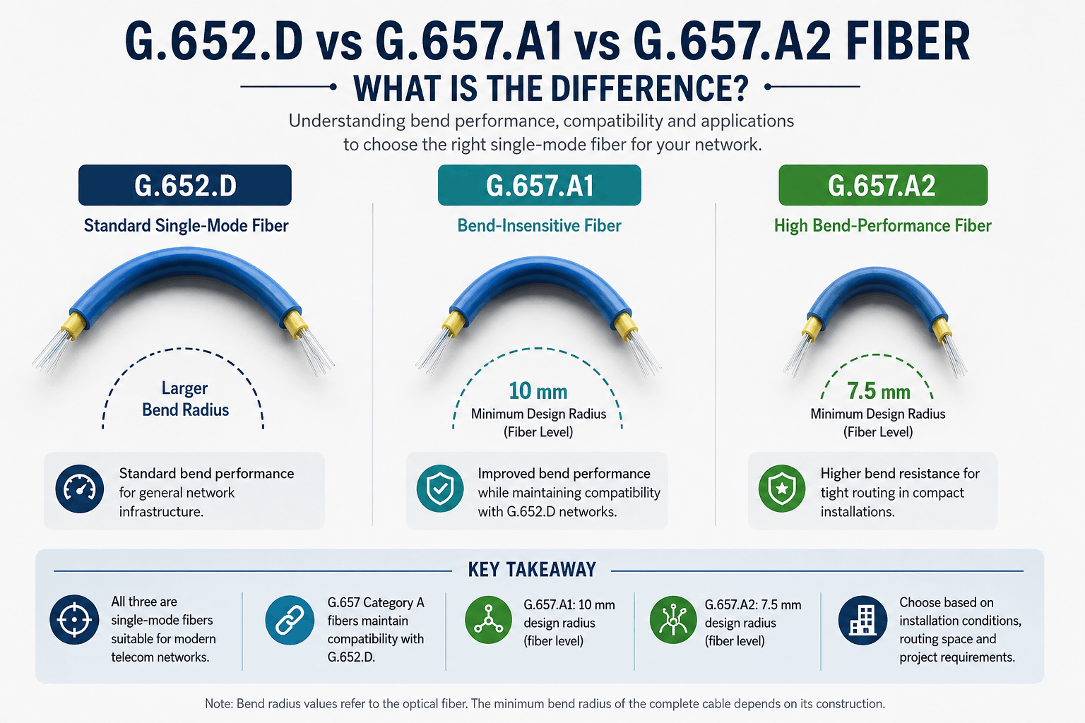
G.652.D vs G.657.A1 vs G.657.A2 Fiber: What Is the Difference?
Reading Time: 9 minutes
Choosing between G.652.D, G.657.A1 and G.657.A2 fiber is primarily a question of how the optical fiber will behave when the network is routed, managed and installed. All three are single-mode fiber types used in modern telecommunications networks, but they are not optimized for exactly the same physical conditions.
G.652.D remains one of the most established single-mode fibers for telecommunications backbones and general network infrastructure. G.657.A1 provides improved resistance to bending while retaining compatibility with G.652.D networks. G.657.A2 extends bend performance further, making it particularly useful where fiber must pass through tighter pathways, compact closures, distribution boxes or building environments.
The practical difference is therefore not simply transmission distance or network speed. For many projects, the most important distinction is macrobending performance and installation flexibility.
Quick answer: G.652.D is a widely used general-purpose single-mode fiber for telecom and backbone networks. G.657.A1 retains G.652.D-compatible transmission characteristics while supporting tighter bends. G.657.A2 provides still greater bend resistance and is especially useful in FTTH, building distribution and other space-constrained installations.
G.652.D vs G.657.A1 vs G.657.A2 at a Glance
| Fiber Type | Main Characteristic | Bend Performance | Typical Applications | Key Selection Consideration |
|---|---|---|---|---|
| G.652.D | Established general-purpose single-mode fiber | Standard bend performance | Telecom backbones, metropolitan networks, long network routes, general outside plant | Reliable choice where tight routing is not a major concern |
| G.657.A1 | G.652.D-compatible bend-insensitive fiber | Improved; suitable for smaller bending radii | Access networks, FTTH distribution, indoor/outdoor networks, high-density infrastructure | Good balance between compatibility and bend resistance |
| G.657.A2 | Higher bend-performance Category A fiber | Greater resistance to tight bending | FTTH drops, buildings, compact pathways, termination areas, dense fiber management | Preferred where routing space and bend radius are more demanding |
One point should be clear from the beginning: these designations describe the optical fiber itself, not the complete fiber optic cable.
A cable also includes elements such as loose tubes or tight buffers, strength members, water-blocking materials, armour and outer jackets. Those elements influence mechanical performance and the permitted installation bend radius of the finished cable.
What Is G.652.D Fiber?
ITU-T G.652.D is an established single-mode optical fiber specification widely used in telecommunications networks.
G.652 fiber was originally optimized around the 1310 nm wavelength region, where chromatic dispersion is low, while also supporting transmission in the 1550 nm region. The G.652.D variant provides transmission characteristics suitable across a broad wavelength range used in modern optical networks.
Its widespread deployment has made G.652.D a familiar choice for network operators, contractors, consultants and telecommunications infrastructure projects.
Typical Applications of G.652.D
G.652.D fiber can be found in applications such as:
- Long-distance telecommunications networks
- Metropolitan fiber networks
- Telecom backbone infrastructure
- Duct fiber optic cables
- Aerial fiber optic networks
- Campus backbone networks
- Industrial communication infrastructure
- General outside-plant fiber networks
Where fiber routes are relatively controlled and very tight bending is not expected, G.652.D continues to provide a practical solution.
Where Does G.652.D Have a Limitation?
The main reason engineers may specify G.657 fiber instead of G.652.D is not that G.652.D lacks transmission capacity. The distinction is primarily related to bending loss.
When an optical fiber is bent too tightly, some of the guided light can escape from the fiber structure. This phenomenon can increase optical loss and reduce the available power margin of the link.
G.652.D was not specifically developed to provide the enhanced macrobending resistance offered by G.657 fibers.
This becomes increasingly important as networks move from long, relatively straightforward backbone routes toward dense access networks, apartment buildings, FTTH distribution points and compact fiber management systems.
What Is G.657.A1 Fiber?
G.657.A1 is a bend-insensitive single-mode fiber designed to offer improved performance when the fiber must follow smaller-radius routes.
An important advantage is compatibility.
G.657 Category A fibers maintain transmission and interconnection characteristics compatible with G.652.D. This makes G.657.A1 particularly useful where improved bend performance is required without moving away from established G.652.D-based network architecture.
According to the G.657 framework, G.657.A1 is appropriate for a minimum design radius of 10 mm at the fiber level.
Where Is G.657.A1 Commonly Used?
G.657.A1 can be an effective option for:
- FTTH access networks
- Fiber distribution networks
- Indoor/outdoor optical cables
- Telecommunications access infrastructure
- High-density fiber cables
- Building backbone networks
- Compact fiber management systems
- Networks requiring compatibility with existing G.652.D infrastructure
It is therefore useful to think of G.657.A1 not as a replacement for an entirely different transmission technology, but as a single-mode fiber that adds greater tolerance to bending while preserving compatibility with conventional network environments.
What Is G.657.A2 Fiber?
G.657.A2 takes the bend-performance concept further.
Like G.657.A1, it belongs to Category A and retains compatibility with G.652.D transmission and interconnection characteristics. However, it is designed to tolerate tighter bends with lower macrobending loss.
G.657.A2 is appropriate for a minimum design radius of 7.5 mm at the fiber level.
This additional flexibility becomes valuable toward the access and customer side of the network, where fiber routes can be considerably more constrained than in an outside-plant backbone.
Typical Applications of G.657.A2
G.657.A2 can be particularly useful for:
- FTTH drop cables
- Apartment and residential fiber networks
- Fiber distribution boxes
- Building risers
- Telecommunications rooms
- Compact ducts and pathways
- Wall outlets and termination points
- High-density optical distribution systems
- Indoor fiber installations with limited routing space
The advantage is not simply that the fiber can physically bend. The objective is to reduce the additional optical loss that can occur when bends become tighter.
What Is Bend-Insensitive Single-Mode Fiber?
Bend-insensitive fiber is designed to reduce the optical power loss caused by bending.
In practical installations, fiber is rarely placed in a perfectly straight route. It passes through trays, ducts, closures, cabinets, racks, wall boxes and termination points. Every change in direction introduces some degree of bending.
When a bend becomes sufficiently tight, conventional single-mode fiber can experience increased macrobending loss.
G.657 fibers modify the optical design so that more of the transmitted light remains effectively confined when the fiber follows a smaller radius.
This characteristic can provide greater installation tolerance, particularly in:
- High-density network environments
- FTTH infrastructure
- Compact termination systems
- Building distribution networks
- Fiber management trays
- Locations where pathway space is limited
However, the term “bend-insensitive” should not be interpreted as “impossible to damage by bending.”
Every optical cable and fiber system still has mechanical and installation limits that must be respected.
G.652.D vs G.657.A1: What Is the Difference?
The most important distinction between G.652.D and G.657.A1 is macrobending performance.
Both are single-mode fibers suitable for modern telecommunications networks. G.657.A1 was designed to retain the transmission and interconnection properties expected from G.652.D-compatible networks while offering improved performance under tighter bending conditions.
| Requirement | G.652.D | G.657.A1 |
|---|---|---|
| General telecom backbone use | Highly suitable | Suitable |
| Compatibility with G.652.D networks | Native reference type | Compatible |
| Enhanced bend resistance | Not its primary design objective | Yes |
| Compact access installations | Possible when bend requirements are controlled | Better suited |
| High-density fiber management | Less optimized for tight routing | More installation flexibility |
| Fiber-level design radius | Follow applicable fiber/cable requirements | 10 mm for G.657.A1 design conditions |
For a long outdoor backbone with generous cable pathways, G.652.D may provide everything the project requires.
For an access network that transitions through cabinets, building entrances and higher-density fiber management points, G.657.A1 can offer additional installation tolerance.
G.657.A1 vs G.657.A2: What Is the Difference?
G.657.A1 and G.657.A2 share the same general objective: improved bending performance while maintaining compatibility with G.652.D network characteristics.
The difference is the level of bend resistance.
G.657.A1 is appropriate for a 10 mm minimum design radius at the fiber level.
G.657.A2 reduces this to 7.5 mm and has more demanding macrobending-loss requirements.
| Characteristic | G.657.A1 | G.657.A2 |
|---|---|---|
| Fiber category | G.657 Category A | G.657 Category A |
| G.652.D compatibility | Yes | Yes |
| Bend resistance | High | Higher |
| Minimum design radius at fiber level | 10 mm | 7.5 mm |
| Access network use | Very suitable | Very suitable |
| Space-constrained installation | Suitable | Particularly suitable |
| FTTH drop and termination areas | Suitable | Often preferred where bends are tighter |
G.657.A2 is therefore most valuable where the physical route genuinely benefits from tighter bending capability.
If the project does not impose particularly demanding bend conditions, specifying G.657.A2 instead of G.657.A1 does not automatically provide a meaningful operational advantage.
Does G.657.A2 Transmit Data Faster Than G.652.D?
No.
The G.652.D, G.657.A1 and G.657.A2 classifications should not be treated as network speed categories.
Moving from G.652.D to G.657.A2 does not automatically change a link from 10 Gb/s to 100 Gb/s or increase the data rate of the installed equipment.
The G.657 distinction primarily addresses bending-loss performance while maintaining the transmission characteristics required for single-mode network applications.
Actual system capacity depends on factors such as:
- Optical transceivers
- Transmission wavelength
- Link length
- Connector and splice losses
- Chromatic dispersion
- Optical power budget
- Network architecture
- Transmission technology
Fiber selection and network speed are therefore related aspects of system design, but they are not the same specification.
Which Single-Mode Fiber Should You Choose?
| Project Situation | Fiber to Consider | Reason |
|---|---|---|
| Long-distance telecom backbone with controlled routing | G.652.D | Established general-purpose single-mode solution |
| Metro or access network requiring better bend tolerance | G.657.A1 | Combines G.652.D compatibility with improved bending performance |
| High-density fiber cable | G.657.A1 or G.657.A2 | Improved macrobending performance can support compact fiber management |
| FTTH distribution network | G.657.A1 or G.657.A2 | Access networks frequently contain more constrained routes |
| FTTH drop cable or compact building route | G.657.A2 | Greater bend resistance is useful near subscribers and termination points |
| Building installation with very limited routing space | G.657.A2 | Designed for tighter fiber-level bending conditions |
| Existing network specified around G.652.D characteristics | G.652.D or G.657 Category A according to project requirements | G.657 Category A retains compatibility with G.652.D transmission characteristics |
The correct decision depends on where the fiber will be installed, how it will be managed and whether the project genuinely benefits from enhanced bending performance.
Does Fiber Type Determine the Cable Bend Radius?
No. This distinction is extremely important for project specifications.
The bending values associated with G.657.A1 and G.657.A2 describe the characteristics of the optical fiber. They should not automatically be used as the minimum installation bend radius of the complete fiber optic cable.
The finished cable may contain:
- Loose tubes
- Tight buffers
- Central strength members
- Aramid yarns
- Water-blocking elements
- Steel tape armour
- Steel wire armour
- Multiple outer sheaths
These components change the mechanical behavior of the complete cable.
A heavily armored outdoor cable containing G.657.A2 fiber, for example, cannot automatically be bent to a 7.5 mm cable radius simply because the optical fiber inside is G.657.A2.
Installers and project engineers should always follow the minimum bending radius stated in the cable manufacturer’s technical datasheet.
Fiber Type and Cable Construction Should Be Specified Separately
Another common procurement mistake is treating the optical fiber type as if it fully describes the cable.
A specification such as:
24F G.657.A1 fiber optic cable
still leaves many important questions unanswered.
The manufacturer would also need to know whether the project requires:
- Single loose tube or multi loose tube construction
- Indoor, outdoor or indoor/outdoor use
- Duct installation
- Aerial installation
- Direct burial capability
- Metallic or non-metallic design
- Steel tape or steel wire armour
- PE or LSZH outer jacket
- Specific CPR classification
- Dry-core or gel-filled water blocking
The optical fiber standard and the cable construction therefore solve different parts of the engineering problem.
Common Mistakes When Selecting G.652.D or G.657 Fiber
1. Assuming G.657.A2 Is Automatically Better for Every Network
G.657.A2 provides higher bend resistance, but this does not mean every backbone or outside-plant project requires it.
If the route provides generous bending radii and the specification is already optimized around G.652.D, selecting a more bend-tolerant fiber may provide little practical benefit.
2. Treating Bend Resistance as Network Speed
G.657.A2 is not a higher-speed version of G.652.D. The primary distinction is macrobending behavior.
3. Confusing Fiber Bend Radius with Cable Bend Radius
The optical fiber may tolerate a very small design radius, while the complete armored or multi-layer cable may require a much larger installation radius.
4. Selecting Fiber Type Without Considering the Route
The appropriate choice depends heavily on whether the cable will run through long outdoor ducts, compact apartment pathways, distribution boxes, data cabinets or other constrained areas.
5. Specifying Only the Fiber Standard in an RFQ
The fiber designation does not define cable armour, tube construction, jacket material, fire classification or environmental protection.
6. Assuming All G.657 Fibers Are the Same
G.657 includes multiple subcategories with different bending characteristics. A project specifying G.657 should identify the required subcategory rather than using only the generic standard number.
What Should a Buyer Include in a Fiber Optic Cable RFQ?
A complete request for quotation helps the manufacturer identify the correct cable design and reduces the risk of technical misunderstanding.
For single-mode fiber optic cables, buyers should consider specifying:
- Required optical fiber type: G.652.D, G.657.A1 or G.657.A2
- Fiber count
- Single loose tube, multi loose tube or tight-buffered construction
- Indoor, outdoor or indoor/outdoor application
- Duct, aerial, direct burial or tray installation
- Required armour or mechanical protection
- Metallic or all-dielectric construction
- Outer jacket material
- Required CPR Euroclass where applicable
- Water-blocking construction
- Maximum tensile and crush requirements where specified
- Required cable diameter or weight limits
- Applicable IEC, ITU-T or project standards
- Drum lengths and packaging requirements
- Required inspection, testing and certification documentation
This provides a much clearer technical basis than requesting only “single-mode fiber optic cable.”
ETK Kablo Single-Mode Fiber Optic Cable Solutions
ETK Kablo manufactures fiber optic cables with G.652.D, G.657.A1 and G.657.A2 single-mode optical fiber options for telecommunications, access networks, enterprise infrastructure, industrial projects and building applications.
Depending on the product family and project specification, these fibers can be incorporated into different cable constructions including duct, aerial, indoor, indoor/outdoor and mechanically protected designs.
G.652.D provides a well-established solution for general telecommunications infrastructure. G.657.A1 offers additional bend tolerance for access and high-density network applications, while G.657.A2 can provide greater installation flexibility where optical fibers must be managed through tighter routes.
The fiber type should always be selected together with the physical cable design. Tube construction, jacket material, mechanical protection, installation environment and fire requirements can be just as important as the optical fiber specification itself.
Frequently Asked Questions
What is the main difference between G.652.D and G.657.A1?
Both are single-mode fibers suitable for telecommunications networks, but G.657.A1 provides improved macrobending performance. It also retains transmission and interconnection compatibility with G.652.D network characteristics.
What is the difference between G.657.A1 and G.657.A2?
G.657.A2 provides greater bend resistance. G.657.A1 is appropriate for a 10 mm minimum design radius at the fiber level, while G.657.A2 extends this to 7.5 mm.
Is G.657.A1 compatible with G.652.D?
Yes. G.657 Category A fibers are designed to maintain transmission and interconnection characteristics compatible with G.652.D.
Is G.657.A2 compatible with G.652.D?
Yes. G.657.A2 belongs to G.657 Category A and maintains compatibility with G.652.D transmission characteristics while providing improved bend performance.
Is G.657.A2 better than G.657.A1?
G.657.A2 provides greater bend tolerance, but it is not automatically the better choice for every project. G.657.A1 may already provide sufficient bend performance where routing conditions are less demanding.
Is G.652.D suitable for FTTH?
G.652.D can be used in optical access networks, but G.657 Category A fibers are often more attractive in sections where tighter routing and bend tolerance are important, particularly closer to buildings and subscribers.
Which fiber is best for FTTH drop cables?
G.657.A2 is commonly suitable for FTTH drop and building applications because of its enhanced macrobending performance. The final selection should still follow the project specification and complete cable design.
Which fiber is best for long-distance networks?
G.652.D remains a widely established option for long-distance and general telecommunications infrastructure. G.657 Category A fibers can also be used where G.652.D characteristics are required, particularly when additional bending performance is beneficial.
Can G.652.D and G.657.A1 fibers be spliced together?
G.657 Category A fibers are designed for compatibility with G.652.D transmission and interconnection characteristics. Actual splice performance still depends on fiber geometry, splicing equipment, preparation and field conditions.
Does using G.657.A2 allow the complete cable to bend to 7.5 mm?
No. The 7.5 mm figure relates to the optical fiber design conditions. The minimum bend radius of the complete cable depends on its construction and must be taken from the cable manufacturer’s technical datasheet.
Conclusion
The difference between G.652.D, G.657.A1 and G.657.A2 fiber is primarily about how much bending flexibility the network requires.
G.652.D remains a proven single-mode fiber for telecommunications backbones and general infrastructure. G.657.A1 maintains compatibility with G.652.D network characteristics while improving macrobending performance. G.657.A2 extends that bend resistance further for compact access networks, FTTH distribution and space-constrained building applications.
The highest bend-performance classification is not automatically the correct specification for every project. Fiber selection should reflect the physical network route, required installation flexibility, existing infrastructure and complete cable construction.
By defining both the optical fiber type and the cable design during procurement, engineers and buyers can obtain a fiber optic cable that matches the real mechanical and transmission requirements of the network.
Benzer yazılar
SWA Fiber Optic Cable: The Ultimate Guide to Steel Wire Armoured Connectivity Solutions
What Is SWA Fiber Optic Cable?
A SWA Fiber Optic Cable, or Steel Wire Armoured Fibre Optic Cable, is a type of armored fiber cable d...


