





 President’s Message
Blog
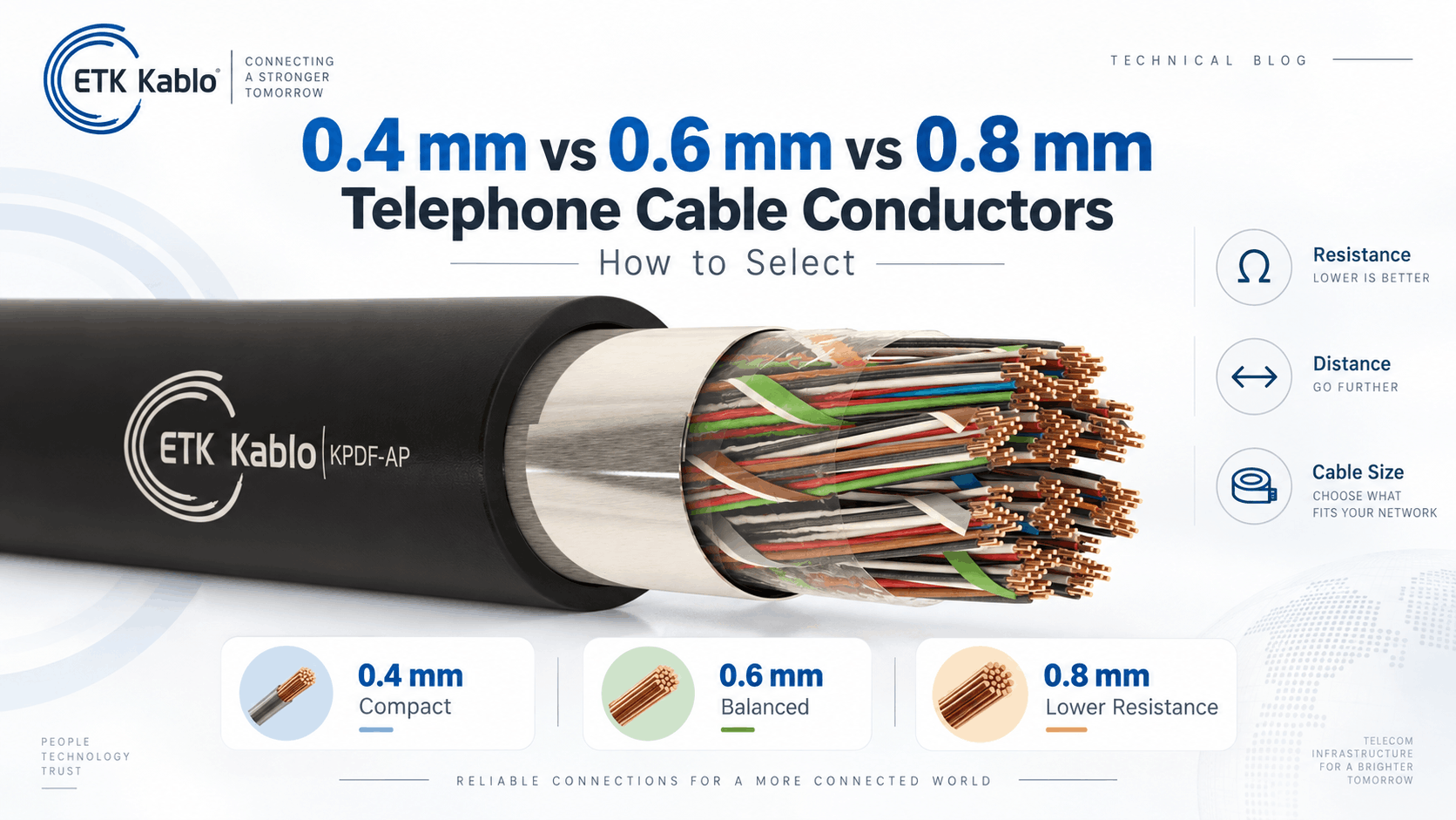
0.4 mm vs 0.6 mm vs 0.8 mm Telephone Cable Conductors: How to Select
Reading Time: 16 minutes
Telephone cable conductor diameter directly affects electrical resistance, transmission performance, copper content, cable size, weight and project cost. For outdoor copper telephone cables, 0.4 mm, 0.6 mm and 0.8 mm are three common conductor diameters, but they are intended for different combinations of transmission distance and network capacity.
A larger conductor contains more copper cross-sectional area. Therefore, it has lower electrical resistance per kilometre. In practical terms, a 0.8 mm conductor can support longer copper loops with substantially less resistive loss than a 0.4 mm conductor of the same material.
However, larger is not automatically better. Increasing conductor diameter also increases copper consumption, overall cable diameter, weight, drum load and installation requirements. The effect becomes especially important in high-pair-count telephone cables containing hundreds of copper conductors.
Consequently, engineers should select conductor diameter according to the required transmission distance and electrical performance rather than simply specifying the largest conductor available.
Quick answer: 0.4 mm telephone cable conductors provide the most compact and economical solution for shorter distribution routes. 0.6 mm offers substantially lower conductor resistance and is a strong middle-ground choice for longer local networks. 0.8 mm provides much lower resistance and is particularly useful for long copper loops or circuits where voltage drop and transmission loss must be minimized. However, 0.8 mm also increases copper weight and finished cable size significantly.
Telephone Cable Conductor Diameter at a Glance
| Characteristic | 0.4 mm | 0.6 mm | 0.8 mm |
|---|---|---|---|
| Approx. copper area | 0.126 mm² | 0.283 mm² | 0.503 mm² |
| ETK max. average resistance at 20°C | 139.4 Ω/km | 62.1 Ω/km | 35 Ω/km |
| Relative conductor area vs 0.4 mm | 1.00× | 2.25× | 4.00× |
| Resistance level | Highest | Medium | Lowest |
| Copper consumption | Lowest | Medium | Highest |
| Typical positioning | Shorter local distribution | Medium / longer routes | Longer copper loops |
| Cable size and weight | Lowest | Higher | Highest |
Therefore, the main engineering trade-off is straightforward: increasing telephone cable conductor diameter reduces electrical resistance but increases the physical and commercial size of the cable.
What Does 0.4 mm, 0.6 mm or 0.8 mm Actually Mean?
The value refers to the nominal diameter of the solid copper conductor itself.
For example:
- 0.4 mm = copper conductor approximately 0.4 mm in diameter
- 0.6 mm = copper conductor approximately 0.6 mm in diameter
- 0.8 mm = copper conductor approximately 0.8 mm in diameter
This measurement should not be confused with conductor cross-sectional area expressed in mm².
That distinction is particularly important because control, instrumentation and power cables are frequently specified as 0.5 mm², 0.75 mm², 1.0 mm² or 1.5 mm².
Telephone cable conductors, by contrast, are traditionally identified by their diameter.
Telephone Cable Conductor Diameter vs mm²
The approximate geometric area of a round conductor can be calculated from:
A = π × d² / 4
Using that formula:
| Conductor Diameter | Approx. Cross-Sectional Area |
|---|---|
| 0.4 mm | 0.126 mm² |
| 0.6 mm | 0.283 mm² |
| 0.8 mm | 0.503 mm² |
Therefore, a 0.8 mm telephone conductor is approximately equivalent to 0.50 mm² of geometric copper area.
Importantly, this does not mean that a product marked 0.8 mm is a 0.8 mm² cable.
Why Diameter Changes Resistance So Much
Electrical resistance is inversely proportional to conductor cross-sectional area when material, temperature and length remain comparable.
However, conductor area increases with the square of diameter.
Therefore, doubling conductor diameter from 0.4 mm to 0.8 mm does not merely double the copper area.
It approximately quadruples it.
As a result:
- 0.6 mm has approximately 2.25 times the copper area of 0.4 mm
- 0.8 mm has approximately 4 times the copper area of 0.4 mm
This geometric relationship explains the substantial reduction in conductor resistance.
0.4 mm vs 0.6 mm vs 0.8 mm Conductor Resistance
ETK Kablo’s A-02YSF(L)2Y / KPDF-AP outdoor telephone cable provides a useful real-world comparison.
| Telephone Cable Conductor Diameter | Maximum Average Resistance at 20°C | Maximum Individual Resistance |
|---|---|---|
| 0.4 mm | 139.4 Ω/km | 146.6 Ω/km |
| 0.6 mm | 62.1 Ω/km | 64.6 Ω/km |
| 0.8 mm | 35 Ω/km | 37 Ω/km |
The difference is substantial.
Compared with 0.4 mm:
- 0.6 mm has roughly 55% lower maximum average conductor resistance
- 0.8 mm has roughly 75% lower maximum average conductor resistance
Consequently, larger copper conductors can carry a low-frequency signal or DC feed across a longer route with much less resistive loss.
Why Telephone Cable Resistance Is Specified Per Conductor
Datasheets normally state DC resistance for one copper conductor.
However, a communication circuit normally uses two conductors forming a pair.
The electrical signal therefore travels through an outgoing conductor and returns through the second conductor.
For a simple loop, conductor resistance must effectively be counted twice.
Using ETK’s maximum average values as an illustrative example, a one-kilometre pair would have approximately:
| Diameter | One Conductor | Approx. 1 km Pair Loop |
|---|---|---|
| 0.4 mm | 139.4 Ω | 278.8 Ω |
| 0.6 mm | 62.1 Ω | 124.2 Ω |
| 0.8 mm | 35 Ω | 70 Ω |
Therefore, conductor diameter becomes increasingly important as loop length increases.
Illustrative Voltage Drop by Conductor Diameter
Consider a simplified DC circuit carrying 20 mA over a one-kilometre cable pair.
Using the approximate loop resistances above:
| Diameter | Approx. Loop Resistance | Illustrative Voltage Drop at 20 mA |
|---|---|---|
| 0.4 mm | 278.8 Ω | 5.58 V |
| 0.6 mm | 124.2 Ω | 2.48 V |
| 0.8 mm | 70 Ω | 1.40 V |
This calculation is only an electrical illustration rather than a universal telephone-system design rule.
Nevertheless, it clearly demonstrates why larger conductors can become attractive for remotely powered or long-loop copper communication circuits.
0.4 mm Telephone Cable Conductors
0.4 mm is a highly efficient conductor size where the route does not require extremely low DC resistance.
Because the copper conductor is smaller, manufacturers can produce more compact high-pair-count cables.
Potential advantages include:
- Lower copper consumption
- Lower cable weight
- Smaller outside diameter
- Higher pair density within ducts
- Easier drum handling
- Lower material cost
Therefore, 0.4 mm is particularly attractive for distribution networks where many pairs must fit into limited infrastructure space.
When 0.4 mm Telephone Cable Makes Sense
A 0.4 mm construction can be appropriate when:
- Routes are relatively short
- Loop resistance remains within system limits
- High pair counts are required
- Duct capacity is limited
- Weight should be minimized
- Copper cost is an important project consideration
For these applications, specifying 0.8 mm simply to obtain a larger conductor can create unnecessary physical and commercial cost.
Limitations of 0.4 mm Conductors
The primary disadvantage is higher electrical resistance.
As route length increases, resistance accumulates proportionally.
For example, a two-kilometre route has approximately twice the conductor resistance of a one-kilometre route when temperature and other conditions remain equivalent.
Consequently, 0.4 mm becomes progressively less attractive for long copper loops where voltage drop and transmission loss matter.
0.6 mm Telephone Cable Conductors
0.6 mm offers a useful middle ground between compact 0.4 mm cable and much heavier 0.8 mm construction.
Its geometric copper area is approximately 0.283 mm².
More importantly, ETK’s KPDF-AP specification limits maximum average conductor resistance to 62.1 Ω/km at 20°C.
That is less than half the corresponding 0.4 mm value.
Therefore, 0.6 mm can significantly extend practical copper-loop capability without moving directly to the largest common conductor size.
When 0.6 mm Telephone Cable Makes Sense
0.6 mm can be a strong choice when:
- Network distances are moderate to long
- 0.4 mm produces excessive loop resistance
- 0.8 mm would create excessive diameter or weight
- Reasonable spare transmission margin is desired
- The cable still needs substantial pair capacity
For many infrastructure projects, this balance between electrical performance and physical size makes 0.6 mm particularly practical.
0.8 mm Telephone Cable Conductors
0.8 mm provides approximately four times the geometric copper area of 0.4 mm.
As a result, conductor resistance falls dramatically.
ETK’s published maximum average value is approximately 35 Ω/km at 20°C.
This makes 0.8 mm attractive where long loops or low-resistance circuits are required.
However, the electrical benefit comes with substantially more copper.
When 0.8 mm Telephone Cable Makes Sense
0.8 mm should be considered when:
- Long transmission distances are required
- DC loop resistance must remain low
- Voltage drop is important
- Remote equipment is fed through the pair
- Transmission margin is critical
- Pair count is moderate enough that increased cable size remains practical
Therefore, 0.8 mm is often an engineering solution to a specific resistance requirement rather than a universal premium version of telephone cable.
0.4 mm vs 0.6 mm vs 0.8 mm at the Same Pair Count
The effect of conductor diameter becomes especially clear when pair count remains constant.
Consider ETK’s 10-pair KPDF-AP quad constructions.
| Conductor Diameter | Approx. Cable OD | Copper Weight | Approx. Total Weight |
|---|---|---|---|
| 0.4 mm | 8.2 mm | 23.7 kg/km | 80 kg/km |
| 0.6 mm | 11 mm | 53.4 kg/km | 134 kg/km |
| 0.8 mm | 12 mm | 94.8 kg/km | 195 kg/km |
Therefore, moving from 0.4 to 0.8 mm increases copper content by approximately four times even though pair count remains exactly the same.
Telephone Cable Conductor Diameter and High Pair Counts
The impact becomes much greater when hundreds of pairs are involved.
For example, ETK’s 100-pair KPDF-AP quad range illustrates the difference.
| Diameter | Approx. Cable OD | Copper Weight | Total Cable Weight |
|---|---|---|---|
| 0.4 mm | 18 mm | 241.6 kg/km | 456 kg/km |
| 0.6 mm | 26 mm | 543.6 kg/km | 961 kg/km |
| 0.8 mm | 33 mm | 966.3 kg/km | 1585 kg/km |
This comparison demonstrates why telephone cable conductor diameter becomes a major project-cost and logistics parameter in high-pair-count networks.
0.8 mm Is Not Always Better
The resistance advantage of 0.8 mm is undeniable.
However, using it where the circuit does not require low resistance can create significant disadvantages.
These can include:
- Higher copper cost
- Larger cable diameter
- Higher total cable weight
- Lower cable density within ducts
- Larger bend requirements
- Heavier drums
- Greater pulling forces
Therefore, conductor selection should be optimized rather than maximized.
0.4 mm Is Not Automatically Inferior
Likewise, 0.4 mm should not be treated as a lower-quality cable.
If a short route satisfies all resistance and transmission requirements with 0.4 mm conductors, the smaller construction can actually be the better engineering choice.
It reduces material use and installation load while maintaining the required network performance.
Consequently, conductor diameter is a sizing decision rather than a product-quality grade.
Telephone Cable Conductor Diameter and Attenuation
Attenuation describes signal loss as a communication signal travels along the cable.
Conductor resistance contributes to attenuation, particularly in low-frequency copper transmission systems.
Therefore, larger copper conductors can generally help reduce resistive loss.
However, attenuation also depends on:
- Frequency
- Mutual capacitance
- Dielectric loss
- Pair geometry
- Insulation design
- Transmission-system characteristics
For this reason, conductor diameter should not be used as a substitute for actual attenuation data when the project specifies frequency-dependent transmission requirements.
Telephone Cable Conductor Diameter and Capacitance
Increasing conductor diameter does not simply reduce capacitance in the same way that it reduces resistance.
Capacitance depends on the relationship between conductor geometry and the surrounding dielectric.
Manufacturers can adjust:
- Insulation thickness
- Pair spacing
- Foam level
- Twist geometry
to control finished-cable capacitance.
Therefore, capacitance should always be checked directly from the cable specification.
ETK Capacitance Example
In ETK’s A-02YSF(L)2Y foam-skin telephone cable range, the published maximum average mutual capacitance is:
- 0.4 mm: 50 nF/km
- 0.6 mm: 45 nF/km
- 0.8 mm: 45 nF/km
Meanwhile, maximum individual values are 56 nF/km for 0.4 mm and 51 nF/km for 0.6 and 0.8 mm.
These figures illustrate that electrical design changes together with conductor size rather than being determined by copper diameter alone.
Telephone Cable Conductor Diameter and Insulation Resistance
Insulation resistance describes electrical leakage through the dielectric surrounding the conductor.
Again, this is not simply a function of copper diameter.
In ETK’s KPDF-AP specification:
- 0.4 mm: insulation resistance above 10,000 MΩ·km
- 0.6 mm: above 15,000 MΩ·km
- 0.8 mm: above 15,000 MΩ·km
Therefore, the finished insulation system must be evaluated alongside conductor resistance.
Telephone Cable Conductor Diameter and Dielectric Strength
ETK’s published dielectric test requirements also differ across conductor sizes.
For pair-to-pair and pair-to-screen testing over one minute:
| Diameter | ETK Published DC Test Voltage |
|---|---|
| 0.4 mm | 1400 V |
| 0.6 mm | 2000 V |
| 0.8 mm | 2400 V |
However, these values belong to the complete ETK product design and should not be generalized into a universal rule that larger conductors inherently withstand higher voltage.
Telephone Cable Conductor Diameter and Transmission Distance
There is no universal rule stating that 0.4 mm reaches exactly one distance while 0.8 mm reaches another.
Maximum usable distance depends on the application.
Relevant factors include:
- Maximum acceptable loop resistance
- Required receive level
- Signal frequency
- Remote power requirements
- Equipment sensitivity
- System topology
Therefore, conductor diameter should be selected by calculating the electrical budget of the actual system.
Why Loop Resistance Is Often More Useful Than Distance Alone
A statement such as “0.6 mm is suitable for five kilometres” can be misleading without defining the communication system.
A better approach is to determine the maximum allowable loop resistance.
Once that limit is known, the designer can compare conductor resistance per kilometre.
For example, if the system can tolerate 250 Ω of copper loop resistance, the practical cable length will be very different for 0.4, 0.6 and 0.8 mm conductors.
Therefore, electrical limits should drive the route calculation.
Telephone Cable Conductor Diameter and Temperature
Copper resistance increases as conductor temperature rises.
Datasheet resistance values are typically referenced to 20°C.
However, outdoor cables can operate at significantly higher temperatures because of:
- Ambient heat
- Solar exposure
- Buried-soil temperature
- Nearby heat sources
Consequently, a design operating close to its maximum resistance limit should include appropriate temperature consideration rather than relying only on the 20°C datasheet value.
Telephone Cable Conductor Diameter and Copper Cost
Copper is one of the largest material-cost components of a multi-pair telephone cable.
Because conductor area scales with the square of diameter, copper requirement increases rapidly.
At identical pair count and length:
- 0.6 mm uses approximately 2.25 times the conductor copper area of 0.4 mm
- 0.8 mm uses approximately 4 times the conductor copper area of 0.4 mm
Therefore, unnecessary oversizing can have a substantial effect on cable price.
Telephone Cable Conductor Diameter and Cable Weight
Copper is not the only component that increases when the conductor becomes larger.
Larger conductors also require changes to:
- Insulation diameter
- Cable-core diameter
- Wrapping material
- Filling compound
- Metallic screen
- Outer sheath
As a result, total cable weight can increase even faster than the direct copper comparison suggests.
Telephone Cable Conductor Diameter and Duct Space
Duct availability can become a limiting factor in telecommunications infrastructure.
A larger outside diameter occupies more cross-sectional area.
Therefore, upgrading every circuit from 0.4 to 0.8 mm can reduce the number of cables that fit into an existing duct system.
This matters particularly in:
- Urban telecom networks
- Industrial campuses
- Railway infrastructure
- Airports
- Existing underground conduits
Consequently, transmission performance and pathway utilization should be optimized together.
Telephone Cable Conductor Diameter and Bend Radius
Minimum bending radius generally depends on overall cable diameter and construction.
Since larger conductors increase the finished cable diameter, they can indirectly increase the physical space required for bends.
This becomes especially important for:
- Manholes
- Joint chambers
- Duct bends
- Building entries
- Cable trays
Therefore, conductor sizing can influence civil and installation design.
Telephone Cable Conductor Diameter and Drum Size
Larger and heavier cables normally require more substantial drums and can be supplied in shorter practical lengths.
As a result, selecting a larger conductor can influence:
- Transport
- Forklift requirements
- Drum handling
- Storage
- Number of joints
Thus, conductor diameter affects logistics as well as electrical performance.
Pair Count and Conductor Diameter Must Be Selected Together
Pair count and conductor diameter answer two different questions.
Pair count asks: how many circuits are required?
Telephone cable conductor diameter asks: what electrical resistance and transmission performance are required per circuit?
For example, a project might require:
- 500 pairs × 0.4 mm for dense local distribution
- 100 pairs × 0.6 mm for a longer feeder
- 20 pairs × 0.8 mm for long remote circuits
Therefore, the largest pair count and the largest conductor diameter do not necessarily belong together.
0.4 mm for High-Pair-Count Networks
Small conductors become particularly attractive when hundreds or thousands of circuits must be consolidated.
For example, ETK offers 0.4 mm KPDF-AP constructions extending well above 1000 pairs.
The smaller conductor helps control:
- Overall diameter
- Copper weight
- Drum weight
- Duct occupancy
Therefore, 0.4 mm can be an efficient feeder solution when individual loop lengths remain compatible with its higher resistance.
0.8 mm for Long Low-Pair-Count Routes
The reverse situation can also occur.
A remote site might require only a small number of communication pairs but over a relatively long copper route.
In that case, using fewer 0.8 mm pairs can be more logical than installing a large number of smaller high-resistance conductors.
Consequently, network geography should influence conductor selection.
Telephone Cable Conductor Diameter for Duct Applications
Duct installations require a balance between electrical performance and available space.
0.4 mm can maximize pair density where duct occupancy is critical.
0.6 mm can provide a compromise between reach and size.
Meanwhile, 0.8 mm can be justified where electrical reach takes priority over cable compactness.
Therefore, duct diameter and fill calculations should be reviewed before changing conductor size.
Telephone Cable Conductor Diameter for Direct Burial
Direct-burial routes can extend over long distances, potentially increasing the importance of conductor resistance.
However, direct burial also requires the appropriate complete cable construction.
This can include:
- Jelly filling
- Moisture barrier
- PE outer sheath
- Steel tape armour
- Steel wire armour
Therefore, selecting 0.8 mm conductors does not by itself make a cable suitable for direct burial.
Telephone Cable Conductor Diameter for Aerial Networks
Aerial routes can also benefit from larger conductors when spans serve long-distance copper circuits.
However, increasing conductor diameter raises cable weight.
This changes the mechanical loading placed on:
- Messenger wires
- Poles
- Suspension fittings
- Dead-end hardware
Consequently, aerial cable sizing must include both electrical and mechanical calculations.
Telephone Cable Conductor Diameter for Industrial Networks
Industrial sites can use outdoor telephone cables for:
- Intercom systems
- Legacy voice networks
- Alarm circuits
- Security systems
- Low-speed supervisory circuits
- Remote communication points
Route lengths can vary significantly across a large plant.
Therefore, the same project can legitimately use 0.4, 0.6 and 0.8 mm conductors in different network sections.
Telephone Cable Conductor Diameter for Railway Infrastructure
Railway networks can contain communication points distributed over long geographical distances.
Larger copper conductors can become attractive where electrical loop length is high.
However, modern railway systems increasingly use optical fiber for high-capacity digital communications.
Consequently, large-diameter copper should be selected where copper circuits are genuinely required rather than as a substitute for fiber backbone design.
Telephone Cable Conductor Diameter for Rural Telecom Networks
Rural networks can involve long distances between distribution points and subscribers or remote facilities.
In such conditions, 0.6 or 0.8 mm conductors can reduce loop resistance substantially.
However, pair counts may be lower than in dense urban areas.
Therefore, larger conductor diameter and lower pair count can sometimes form a logical combination for rural routes.
Telephone Cable Conductor Diameter vs Fiber Optic Cable
Increasing copper diameter can improve the electrical performance of a copper pair, but it does not transform copper into a high-capacity modern fiber backbone.
Fiber provides:
- Much greater bandwidth
- Much longer high-speed transmission distance
- Immunity to electromagnetic interference
- Lower weight for high-capacity links
Therefore, when the application requires high-speed data rather than legacy voice, analogue or low-frequency communication, optical fiber can be the more appropriate technology regardless of copper conductor diameter.
Does 0.8 mm Mean Better Cable Quality?
No.
A high-quality 0.4 mm cable manufactured within specification is not inferior to a 0.8 mm cable.
They simply serve different electrical and physical design targets.
Cable quality depends on factors such as:
- Copper purity
- Dimensional consistency
- Insulation quality
- Electrical balance
- Pair twisting
- Screening
- Water protection
- Outer-jacket quality
Therefore, conductor diameter should never be used as a standalone measure of product quality.
Does 0.8 mm Always Provide Lower Attenuation?
A larger conductor reduces conductor resistance, which generally supports lower resistive loss.
However, total attenuation also depends on the dielectric and complete transmission design.
Therefore, actual attenuation specifications should be compared where the application requires a defined frequency-dependent transmission limit.
Does 0.8 mm Have Four Times the Copper of 0.4 mm?
Approximately yes, assuming the same number of solid round conductors and equivalent cable length.
The reason is that cross-sectional area varies with the square of diameter.
Doubling diameter from 0.4 to 0.8 mm increases geometric conductor area from approximately 0.126 mm² to 0.503 mm².
That is almost exactly four times the copper area.
Does 0.6 mm Have 50% More Copper Than 0.4 mm?
No.
This is another common misconception.
Although 0.6 mm diameter is only 50% larger than 0.4 mm diameter, its area is approximately 125% larger.
In other words, 0.6 mm has about 2.25 times the cross-sectional copper area.
Therefore, cable cost and weight do not increase linearly with conductor diameter.
IEC 60708 and Telephone Cable Conductor Diameter
IEC 60708 provides the international framework for low-frequency outdoor copper communication cables using polyolefin insulation and moisture-barrier polyolefin sheaths.
The standard addresses cable construction as well as electrical, mechanical and environmental requirements.
Conductor diameter is therefore one component of a complete standardized telephone cable design.
Consequently, procurement specifications should define conductor diameter together with the electrical requirements of the complete cable.
Common Telephone Cable Conductor Diameter Mistakes
Confusing Diameter with Cross-Sectional Area
0.8 mm diameter is approximately 0.50 mm², not 0.8 mm².
Assuming Larger Always Means Better
Larger conductors lower resistance but increase copper, diameter, weight and cost.
Selecting by Distance Alone
The correct parameter is normally allowable loop resistance or transmission performance, not a universal distance limit.
Ignoring Pair Count
A conductor-size increase becomes much more significant when hundreds of pairs are involved.
Ignoring Temperature
Conductor resistance rises as copper temperature increases.
Ignoring Duct Space
Larger conductors can significantly increase overall cable diameter.
Ignoring Drum Weight
High-pair-count 0.8 mm cables can become extremely heavy.
Assuming 0.4 mm Is Low Quality
It is an established engineering size for applications where its resistance is acceptable.
Assuming Conductor Diameter Determines Capacitance
Insulation geometry and dielectric design also play major roles.
Ignoring Insulation Type
Foam-skin and solid PE designs can produce different electrical characteristics even with the same conductor diameter.
Ignoring Water Protection
Diameter does not determine whether a cable needs jelly filling or dry-core water blocking.
Using Copper Where Fiber Is More Appropriate
Increasing conductor diameter does not replace fiber for modern high-bandwidth backbone applications.
How to Select Telephone Cable Conductor Diameter
Define the Circuit Type
Start by identifying voice, alarm, signalling, control or another low-frequency application.
Determine Route Length
Measure the complete electrical route rather than straight-line distance.
Identify Maximum Loop Resistance
Use the connected equipment specification to establish the acceptable resistance budget.
Compare Conductor Resistance
Calculate the expected loop resistance using the manufacturer’s Ω/km value.
Include Temperature Margin
Account for the fact that copper resistance increases above 20°C.
Select Pair Count
Determine how many circuits and spare pairs are required.
Check Finished Cable Diameter
Confirm compatibility with ducts, entries, trays and joint chambers.
Check Cable Weight
Review drum, transport, support and installation requirements.
Select Insulation Construction
Choose foam-skin or solid PE according to the electrical and project specification.
Select Water Protection
Define jelly-filled, dry-core or other water-blocking construction.
Add Mechanical Protection
Specify armour or messenger support where the installation environment requires it.
Telephone Cable Conductor Diameter RFQ Checklist
A professional RFQ should specify more than simply “0.8 mm telephone cable.”
- Required conductor diameter
- Solid annealed copper conductor
- Pair count
- Pair or star-quad construction
- Maximum conductor resistance at 20°C
- Minimum insulation resistance
- Maximum mutual capacitance
- Capacitance unbalance
- Dielectric test requirement
- Foam-skin or solid PE insulation
- Jelly-filled or dry-core construction
- Metallic screen
- PE outer sheath
- UV resistance
- Armour where required
- Messenger wire where required
- Maximum cable outside diameter
- Approximate cable weight
- Required drum length
- Installation environment
- Applicable IEC 60708 requirements
- Required test documentation
Therefore, the cable manufacturer can optimize the complete construction around the required electrical performance.
ETK Kablo 0.4 mm, 0.6 mm and 0.8 mm Telephone Cables
ETK Kablo manufactures outdoor copper telephone cables across a broad range of conductor diameters, including 0.4, 0.5, 0.6, 0.63, 0.65, 0.8 and 0.9 mm depending on the product family.
In the A-02YSF(L)2Y / KPDF-AP family, the conductor consists of solid electrolytic annealed copper surrounded by foam-skin polyethylene insulation.
The cable core is jelly filled, wrapped and protected by a copolymer-coated aluminum moisture barrier and UV-resistant black polyethylene outer sheath.
This allows engineers to select conductor resistance independently from:
- Pair count
- Water protection
- Screening
- Installation method
Therefore, ETK can match telephone cable conductor diameter to the electrical distance and physical requirements of the project.
ETK Electrical Comparison: 0.4 vs 0.6 vs 0.8 mm
| Parameter | 0.4 mm | 0.6 mm | 0.8 mm |
|---|---|---|---|
| Max. avg. conductor resistance | 139.4 Ω/km | 62.1 Ω/km | 35 Ω/km |
| Max. individual conductor resistance | 146.6 Ω/km | 64.6 Ω/km | 37 Ω/km |
| Minimum insulation resistance | >10,000 MΩ·km | >15,000 MΩ·km | >15,000 MΩ·km |
| Max. average mutual capacitance | 50 nF/km | 45 nF/km | 45 nF/km |
| 1 min DC dielectric test | 1400 V | 2000 V | 2400 V |
This data demonstrates why conductor diameter should be treated as a measurable electrical-design variable rather than simply a nominal product option.
Frequently Asked Questions About Telephone Cable Conductor Diameter
What is telephone cable conductor diameter?
It is the nominal diameter of the solid copper conductor inside each insulated telephone-cable wire.
Is 0.8 mm the same as 0.8 mm²?
No. A round 0.8 mm diameter conductor has an approximate cross-sectional area of 0.503 mm².
What area is a 0.6 mm copper conductor?
Approximately 0.283 mm².
What area is a 0.4 mm conductor?
Approximately 0.126 mm².
Which has lower resistance: 0.4 or 0.8 mm?
0.8 mm has much lower resistance because its copper area is approximately four times greater.
What is the resistance of ETK 0.4 mm telephone cable?
ETK’s KPDF-AP specification publishes a maximum average conductor resistance of 139.4 Ω/km at 20°C.
What is the resistance of 0.6 mm telephone cable?
For the same ETK construction, the published maximum average value is 62.1 Ω/km at 20°C.
What is the resistance of 0.8 mm telephone cable?
The corresponding ETK maximum average value is 35 Ω/km at 20°C.
Which conductor is best for long-distance telephone cable?
A larger conductor such as 0.8 mm provides lower resistance and can therefore be advantageous for long loops, but actual selection should be based on the system’s allowable loop resistance.
Is 0.4 mm suitable for outdoor telephone cable?
Yes. It is widely used when the electrical route length and resistance requirements allow it.
Why use 0.6 mm?
0.6 mm offers a strong compromise between the compact size of 0.4 mm and the very low resistance of 0.8 mm.
Why not always use 0.8 mm?
Because it significantly increases copper consumption, cable weight, diameter and cost.
Does larger conductor diameter increase cable diameter?
Yes. Larger copper conductors require larger insulated elements and therefore generally increase the overall cable size.
Does larger conductor diameter increase cable weight?
Yes. Both copper weight and other cable-material requirements increase.
Does larger conductor diameter reduce capacitance?
Not automatically. Capacitance also depends strongly on insulation and pair geometry.
Does larger conductor diameter reduce attenuation?
Lower conductor resistance generally reduces the resistive component of transmission loss, but total attenuation depends on the complete cable design and operating frequency.
What is loop resistance?
It is the combined resistance of the outgoing and return conductors forming the complete electrical circuit.
Does conductor resistance increase with temperature?
Yes. Copper resistance rises as temperature increases.
Can 0.4 mm and 0.8 mm be used in the same network?
Yes. Different network sections can use different conductor sizes according to route length, pair count and resistance requirements.
Does IEC 60708 cover outdoor telephone cables?
Yes. IEC 60708 defines requirements for low-frequency outdoor copper communication cables using polyolefin insulation and moisture-barrier polyolefin sheaths.
How should telephone cable conductor diameter be selected?
Determine route length and allowable loop resistance first, then evaluate pair count, cable diameter, weight, installation environment and complete electrical specifications.
Conclusion
Telephone cable conductor diameter is one of the most important variables in the design of an outdoor copper telecommunications network.
0.4 mm provides the most compact and copper-efficient option, making it highly suitable for shorter routes and dense high-pair-count distribution networks.
0.6 mm more than doubles the copper cross-sectional area compared with 0.4 mm and reduces conductor resistance substantially, providing a strong compromise between electrical reach and physical cable size.
0.8 mm provides approximately four times the copper area of 0.4 mm and reduces ETK’s published maximum average conductor resistance from 139.4 Ω/km to approximately 35 Ω/km.
However, that electrical advantage comes with significantly higher copper content, overall weight and finished cable diameter.
Select Conductor Diameter from the Electrical Requirement
First, establish the route length and maximum permissible loop resistance.
Next, compare the manufacturer’s conductor resistance values at the required diameter.
Then, determine the required pair count and spare capacity.
Afterward, evaluate the resulting cable diameter, weight, drum length and installation requirements.
Finally, select insulation, filling, screening and mechanical protection independently according to the installation environment.
Ultimately, 0.8 mm is not inherently better than 0.6 mm or 0.4 mm. The correct conductor is the smallest diameter that provides the required electrical performance with appropriate engineering margin while keeping the complete cable practical and economical.
Benzer yazılar
EN 45545-2 HL1 vs HL2 vs HL3: Railway Cable Fire Requirements
EN 45545-2 hazard levels define different fire-performance requirements for materials and components installed on railway vehicles. For...
0.4 mm vs 0.6 mm vs 0.8 mm Telephone Cable Conductors: How to Select
Telephone cable conductor diameter directly affects electrical resistance, transmission performance, copper content, cable size, weight...

RE-Y vs RE-2Y vs RE-2X Instrumentation Cable: PVC, PE and XLPE Insulation Compared
RE-Y vs RE-2Y vs RE-2X is fundamentally a comparison of the insulation materials surrounding the copper conductors inside an instrument...
10 Pair vs 50 Pair vs 100 Pair vs 500 Pair Telephone Cable: Selection Guide
Telephone cable pair count is one of the first specifications engineers and procurement teams must define when selecting a multi-pair c...
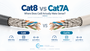
Cat8 vs Cat7A Cable: Where Does Cat8 Actually Make Sense?
Cat8 vs Cat7A is often presented as a simple comparison in which Cat8 is assumed to be the newer, faster and therefore better Ethernet ...
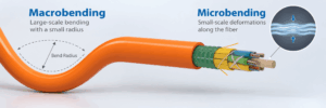
Fiber Optic Cable Bend Radius: Macrobending vs Microbending Explained
Fiber optic bend radius is one of the most important installation limits in an optical cable system. A fiber cable can meet its attenua...

Foam-Skin vs Solid PE Insulation in Telephone Cables
Foam-skin vs solid PE is an important insulation choice in outdoor copper telephone cables because the material surrounding each conduc...

Cat6A Alien Crosstalk Explained: Why ANEXT Matters
Cat6A alien crosstalk is one of the most important performance considerations in high-speed copper structured cabling. As Ethernet freq...

Fiber Optic Cable Mechanical Tests: Tensile, Crush, Impact and Bend Performance
Fiber optic cable testing is essential because good optical performance alone does not prove that a cable can survive installation and ...
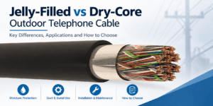
Jelly-Filled vs Dry-Core Outdoor Telephone Cable
Jelly-filled vs dry-core is an important construction choice when specifying outdoor telephone cable for telecom distribution networks,...
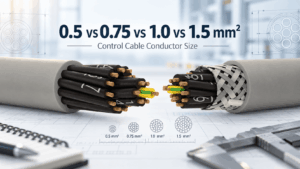
0.5 vs 0.75 vs 1.0 vs 1.5 mm² Control Cable: How to Select Conductor Size
Control cable conductor size affects resistance, voltage drop, current-carrying capability, cable diameter, flexibility and cost. Among...

300/500 V vs 450/750 V Control Cable: When Is the Higher Voltage Rating Required?
Control cable voltage rating is one of the most important electrical parameters to check when selecting cables for industrial machinery...


