





 President’s Message
Blog
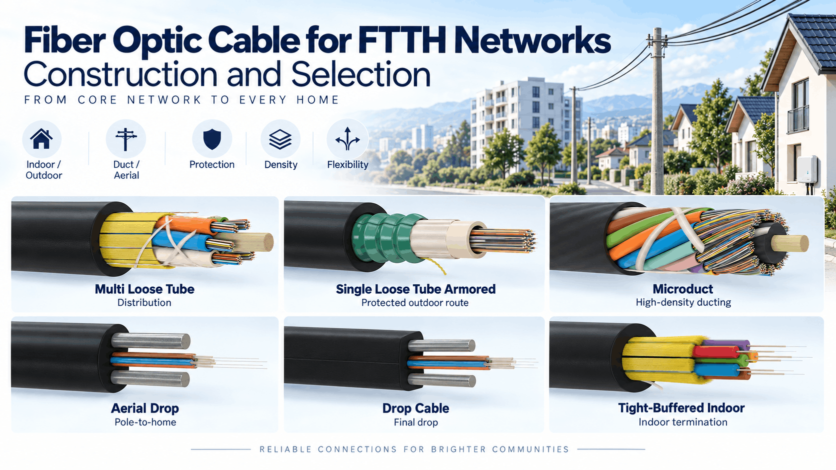
Fiber Optic Cable for FTTH Networks: Construction and Selection
Reading Time: 19 minutes
A FTTH fiber optic cable provides the physical optical pathway that carries broadband connectivity from the operator network toward individual homes, apartments and other subscriber premises. However, an FTTH deployment rarely uses one identical cable construction throughout the complete route.
The feeder network can contain dozens or hundreds of optical fibers. Meanwhile, the distribution network must support efficient branching toward neighborhoods, buildings or access points. Finally, the subscriber drop normally requires only one or a few fibers but places much greater emphasis on compact dimensions, bending performance and straightforward building entry.
Therefore, selecting fiber optic cable for FTTH networks requires engineers to evaluate each network segment independently. Fiber type, fiber count, cable architecture, water blocking, strength members, outer sheath, fire performance, installation method and future expansion strategy can all affect the correct construction.
Bend-insensitive G.657 fiber has become particularly important in access networks because the final part of the route frequently passes around building corners, inside wall boxes, through compact ducts and toward optical network terminals. Nevertheless, conventional G.652.D fiber remains highly relevant for feeder and distribution networks where longer outdoor routes and conventional telecom construction dominate.
Quick answer: High-count loose-tube cables are generally appropriate for FTTH feeder and major distribution sections. Compact duct or microduct cable can increase fiber density in underground access networks. Aerial self-supporting or messenger-supported constructions can serve overhead distribution routes. Subscriber drops typically use one to four G.657 bend-insensitive fibers in compact flat or round constructions. Indoor sections should additionally meet the applicable flame, smoke, halogen and CPR requirements.
FTTH Fiber Optic Cable at a Glance
| FTTH Network Section | Typical Cable Approach | Main Design Priority |
|---|---|---|
| Feeder | High-count loose-tube cable | Capacity, attenuation, route reliability |
| Distribution | Central or multi loose-tube cable | Branching, fiber organization, compactness |
| Microduct distribution | Microduct fiber cable | Small diameter, blowing performance, scalability |
| Underground drop | Compact dielectric drop cable | Small diameter, mechanical protection |
| Aerial drop | Messenger or self-supporting drop | Tensile performance and weather resistance |
| Building entry | Indoor/outdoor cable | Environmental and fire-performance transition |
| Indoor subscriber route | LSZH bend-insensitive drop cable | Small bend radius, safety, compact routing |
Consequently, FTTH cable selection begins with identifying the network section rather than starting with a product designation.
What Is an FTTH Fiber Optic Cable?
An FTTH fiber optic cable is an optical telecommunications cable used within a Fiber to the Home access network.
FTTH brings optical fiber directly to or into the subscriber premises rather than stopping at a roadside cabinet, building basement or intermediate copper distribution point.
A complete FTTH cable network can therefore include:
- Feeder cables
- Distribution cables
- Microduct cables
- Aerial cables
- Underground duct cables
- Drop cables
- Indoor/outdoor cables
- Indoor subscriber cables
Although all of these products carry optical fibers, their mechanical constructions can differ significantly.
FTTH vs FTTB vs FTTC
The term FTTX describes several architectures according to how close the fiber reaches the end user.
| Architecture | Fiber Endpoint |
|---|---|
| FTTH | Home / subscriber premises |
| FTTB | Building |
| FTTC | Street cabinet / curb |
| FTTP | Premises; often used broadly for full-fiber access |
The distinction affects cable design because FTTH extends optical fiber farther into the access network.
As a result, FTTH generally requires a larger number of short distribution and drop sections and creates more branching, termination and bending points.
How an FTTH Optical Distribution Network Is Structured
FTTH networks are commonly organized into several physical sections.
A simplified architecture can include:
- Optical Line Terminal
- Feeder network
- Optical distribution point
- Passive optical splitter
- Distribution network
- Drop cable
- Optical termination point
- Optical Network Terminal
Depending on operator architecture, splitters can be centralized or distributed across more than one point.
Therefore, cable count and fiber organization should be coordinated with the selected splitter architecture.
FTTH Fiber Optic Cable for GPON and XGS-PON
The physical fiber infrastructure can support several passive optical network generations.
Widely deployed and developing systems include:
- GPON
- XG-PON
- XGS-PON
- NG-PON2
- 50G-PON
For example, XGS-PON provides nominal 10 Gbit/s transmission in both downstream and upstream directions.
Meanwhile, current 50G-PON standards extend downstream line rates to 50 Gbit/s and define high-speed upstream options.
Importantly, migration between PON generations does not automatically require replacing the installed fiber cable.
Consequently, high-quality single-mode infrastructure can remain in service while active equipment and wavelength technologies evolve.
Why Fiber Selection Matters for FTTH
The optical fiber inside the cable determines fundamental transmission and bending characteristics.
Common access-network choices include:
- G.652.D
- G.657.A1
- G.657.A2
- G.657.B3 for specialized very-tight-bend applications
However, these fiber types should not be treated as simple generations where the newest designation automatically replaces every older fiber.
Instead, the correct choice depends on route geometry, interoperability and network section.
G.652.D Fiber in FTTH Networks
G.652.D remains one of the most established single-mode fibers for telecommunications networks.
It is optimized around the 1310 nm region while also supporting transmission in the 1550 nm region and broader telecom wavelength applications.
Within an FTTH architecture, G.652.D can be particularly suitable for:
- Feeder routes
- Long outdoor distribution sections
- Metro access networks
- Backbone connections
- Large loose-tube cables
Therefore, the expansion of bend-insensitive fiber does not make G.652.D obsolete for access infrastructure.
Why G.657 Fiber Is Important for FTTH
ITU-T G.657 was developed specifically around the additional bending demands found in access networks and compact fiber-management environments.
Subscriber-side FTTH routes can include:
- Sharp building corners
- Small wall boxes
- Compact closures
- Apartment risers
- Subscriber termination boxes
- Restricted indoor conduits
In these environments, excessive macrobending loss can reduce available optical power.
Therefore, bend-insensitive G.657 fiber can provide significant practical advantages.
G.657.A1 vs G.657.A2 for FTTH Fiber Optic Cable
G.657.A1 and G.657.A2 both provide improved bending performance compared with conventional G.652.D fiber while remaining within the Category A framework.
| Characteristic | G.657.A1 | G.657.A2 |
|---|---|---|
| Fiber family | Bend-insensitive single mode | Bend-insensitive single mode |
| G.652.D compatibility | Yes | Yes |
| Recommended minimum design radius | 10 mm | 7.5 mm |
| Bend performance | High | Higher |
| Typical access role | Distribution / drop / indoor | Drop / indoor / compact routing |
Consequently, G.657.A2 can provide additional bending margin where subscriber routing is especially compact.
What Is G.657.B3?
G.657.B3 is optimized for even smaller bending radii than the Category A fibers.
The current ITU-T recommendation identifies a minimum design radius of approximately 5 mm for B3 fiber.
However, Category B fibers are mainly intended for short-reach access applications near or inside buildings and are not necessarily fully compliant with every G.652.D transmission characteristic.
Therefore, G.657.B3 should be selected deliberately rather than automatically replacing G.657.A2.
G.652.D vs G.657 in FTTH Networks
The two technologies can coexist within one access network.
| Network Requirement | G.652.D | G.657.A1/A2 |
|---|---|---|
| Long outdoor feeder | Strong option | Also possible |
| Conventional telecom backbone | Excellent | Suitable with Category A |
| Tight building bends | Less optimized | Strong advantage |
| Subscriber drop | Possible but less preferred for tight bends | Strong option |
| Indoor subscriber routing | Route-dependent | Particularly suitable |
For this reason, many FTTH designs use conventional telecom fiber in major outdoor routes and bend-insensitive fiber closer to the subscriber.
FTTH Fiber Optic Cable for Feeder Networks
The feeder section carries optical capacity from the central office or aggregation location toward the distribution network.
This part of the route can require relatively high fiber counts such as:
- 48 fibers
- 72 fibers
- 96 fibers
- 144 fibers
- 288 fibers
- Higher counts where network density requires them
Because these cables serve many downstream subscribers, mechanical reliability and spare capacity become particularly important.
Accordingly, feeder cables commonly use loose-tube architectures designed for outdoor telecom networks.
Central Loose Tube FTTH Fiber Optic Cable
A central loose-tube construction places the optical fibers inside one primary PBT tube.
The architecture can provide:
- Compact outside diameter
- Simple cable geometry
- Good moisture protection
- Efficient low-to-medium fiber counts
- Low cable weight
Therefore, central loose-tube cable can work particularly well for smaller FTTH distribution networks and compact aerial or duct routes.
Multi Loose Tube FTTH Cable
Multi loose-tube designs organize several fiber tubes around a central strength member.
This architecture becomes increasingly useful as fiber count rises.
Advantages can include:
- High fiber count
- Organized tube allocation
- Convenient branching
- Mid-span access
- Scalable backbone capacity
As a result, multi loose-tube constructions are widely applicable to major feeder and distribution sections.
Central Loose Tube vs Multi Loose Tube for FTTH
| Characteristic | Central Loose Tube | Multi Loose Tube |
|---|---|---|
| Cable architecture | One main tube | Several stranded tubes |
| Typical fiber counts | Lower to medium | Medium to very high |
| Outside diameter | Very compact | Increases with capacity |
| Tube organization | Simple | Highly structured |
| Branching flexibility | Good | Very good for large networks |
| Typical FTTH role | Distribution | Feeder / distribution |
Neither architecture is universally superior. Instead, fiber count and network branching strategy should determine the construction.
Fiber Count in an FTTH Network
Fiber count should reflect the topology rather than the maximum count that can physically fit inside a cable.
Important inputs include:
- Number of subscribers
- Splitter architecture
- Spare fiber policy
- Future network growth
- Business connections
- Mobile backhaul requirements
- Network redundancy
Consequently, two FTTH projects serving the same number of homes can legitimately use different feeder fiber counts.
Does a 1:32 Splitter Mean You Need 32 Fibers?
No.
A passive optical splitter divides one optical input into multiple output branches.
Therefore, PON architecture can serve multiple subscribers from one feeder fiber.
Nevertheless, network planners still need spare fibers for:
- Future growth
- Business services
- Alternative splitter arrangements
- Fault recovery
- New technologies
Consequently, splitter ratio should not be used as the only input when determining cable fiber count.
FTTH Fiber Optic Cable for Distribution Networks
The distribution section connects major access points toward smaller serving areas or subscriber clusters.
Compared with feeder cable, distribution cable often places greater emphasis on:
- Smaller diameter
- Easier branching
- Mid-span access
- Lower cable weight
- Efficient closure management
For this reason, cable-core architecture becomes especially important in dense access networks.
Why Mid-Span Access Matters in FTTH
A distribution cable can pass several neighborhoods, buildings or access points along one route.
Mid-span access allows selected fibers or loose tubes to be extracted without cutting every fiber inside the cable.
This can reduce unnecessary splicing and preserve through fibers.
Therefore, network planners should consider mid-span access requirements when selecting tube count and cable architecture.
Microduct FTTH Fiber Optic Cable
A microduct FTTH fiber optic cable provides high optical capacity within a small cable diameter and is normally optimized for air-blown installation.
Microduct architecture can allow network operators to install several empty pathways initially and populate them as demand grows.
Advantages can include:
- High fiber density
- Efficient duct utilization
- Incremental network expansion
- Lower cable weight
- Future installation without repeated civil works
Consequently, microduct technology can be particularly attractive for urban FTTH networks where underground pathway capacity is valuable.
Microduct Cable vs Conventional Duct Cable for FTTH
Both constructions can serve underground fiber networks, but their design priorities differ.
| Characteristic | Microduct Cable | Conventional Duct Cable |
|---|---|---|
| Outside diameter | Highly optimized | Generally larger |
| Weight | Low | Potentially higher |
| Installation | Primarily blowing | Pulling or blowing |
| Pathway strategy | Multiple microducts | Main duct |
| Future expansion | Very flexible | Depends on remaining duct space |
Therefore, the choice should follow the complete civil-infrastructure strategy rather than cable diameter alone.
Duct Fiber Optic Cable for FTTH Networks
Conventional duct cable remains widely applicable for underground FTTH feeder and distribution networks.
A suitable design can include:
- PBT loose tubes
- FRP central strength member
- Aramid or glass yarn
- Dry or gel water blocking
- PE or HDPE outer sheath
Because the duct supplies important external mechanical protection, heavy metallic armour is not required in every installation.
As a result, non-metallic constructions can provide efficient pulling and blowing performance.
Water Blocking in FTTH Fiber Optic Cable
Outdoor feeder and distribution routes can encounter moisture inside ducts, chambers and underground infrastructure.
Longitudinal water protection can therefore use:
- Thixotropic filling gel
- Water-swellable yarn
- Water-swellable tape
- Dry loose-tube technology
- Hybrid systems
Importantly, “dry cable” and “gel-free cable” do not always describe exactly the same architecture.
For example, a cable can use gel inside the loose tubes while using dry water-swellable yarn around those tubes.
Dry Core vs Gel-Filled FTTH Cable
Gel-filled constructions provide established longitudinal water protection.
Meanwhile, dry water-blocking systems can simplify field preparation and reduce gel cleaning.
Therefore, selection should consider:
- Outdoor exposure
- Installation environment
- Closure preparation
- Maintenance practices
- Required water-penetration performance
The finished-cable water test is ultimately more meaningful than whether the design is marketed as “dry” or “gel filled.”
What Is an FTTH Drop Cable?
The drop cable forms the final optical connection between the distribution network and the subscriber.
This section normally carries only a small number of fibers.
Typical counts include:
- 1 fiber
- 2 fibers
- 4 fibers
However, the drop cable frequently encounters the most complicated physical route, including building facades, small ducts, corners and subscriber termination points.
Consequently, compact dimensions and bending resistance become critical.
Flat FTTH Drop Cable Construction
Flat drop cable is one of the most recognizable FTTH constructions.
A typical architecture can include:
- One to four optical fibers
- Two parallel strength members
- Flat outer sheath
- Optional aerial messenger
The parallel strength elements help protect the fiber against excessive tensile strain while preserving a compact cable profile.
As a result, flat drop cable can be suitable for short subscriber connections and building-entry routes.
FRP vs Steel Strength Members in Drop Cable
Drop cables can use metallic or dielectric reinforcement.
FRP provides an all-dielectric option with no continuous metallic electrical path.
Steel strength members, by contrast, can provide high strength within a compact dimension.
Therefore, selection should consider:
- Electrical isolation
- Tensile requirement
- Cable diameter
- Operator standard
- Installation environment
FTTH Fiber Optic Cable for Aerial Drops
An aerial drop cable connects a distribution point to the subscriber across an overhead span.
In addition to optical performance, it must withstand:
- Cable self-weight
- Wind
- Temperature variation
- UV radiation
- Installation tension
One common architecture incorporates a dedicated steel messenger connected to the optical section by a web.
Alternatively, all-dielectric self-supporting constructions can be used where the project requires them.
Messenger Wire vs All-Dielectric Aerial Drop
| Characteristic | Messenger Supported | All-Dielectric |
|---|---|---|
| Mechanical support | Dedicated messenger | Dielectric strength system |
| Metal content | Yes | No continuous metallic conductor |
| Electrical isolation | Lower | High |
| Span capability | Design-dependent | Design-dependent |
| Typical use | Subscriber overhead drop | Dielectric overhead access |
Consequently, neither architecture should be selected solely from appearance.
Aerial Distribution Cable vs Aerial Drop Cable
An aerial distribution cable normally carries many more fibers and serves multiple downstream subscribers.
A drop cable, by contrast, usually serves one subscriber or a small number of premises.
Therefore, these two cable categories have different priorities:
- Distribution cable → capacity and branching
- Drop cable → compactness and subscriber access
ADSS Cable in FTTH Networks
ADSS can provide an all-dielectric self-supporting aerial backbone or distribution solution.
Its strength system generally relies on dielectric materials such as aramid yarn rather than a metallic messenger.
ADSS can therefore provide advantages around electrical infrastructure.
However, its design must consider:
- Span length
- Wind loading
- Ice loading where relevant
- Sag
- Maximum operating tension
- UV exposure
Consequently, ADSS should not be confused with a lightweight subscriber drop cable.
FTTH Fiber Optic Cable for Direct Burial
Some FTTH routes do not have a protective duct.
Direct-burial constructions can therefore require additional:
- Crush resistance
- Impact protection
- Rodent protection
- Water blocking
- Durable outer sheath
Possible armor systems include metallic and non-metallic designs.
Therefore, an ordinary duct cable should not automatically be used for direct burial simply because it has a PE jacket.
Armored vs Non-Armored FTTH Cable
Armour should follow actual route risk.
Protected telecom ducts may allow lightweight non-armored cable.
By contrast, severe direct-burial or rodent environments can justify:
- Corrugated steel tape
- Steel wire reinforcement
- Glass yarn protection
- Other project-specific armor
However, every additional armor layer increases cable diameter, weight and stiffness.
Consequently, the strongest possible cable is not automatically the best FTTH cable.
FTTH Fiber Optic Cable for Indoor Networks
Once fiber enters a building, cable requirements can change significantly.
Indoor cable can prioritize:
- Low smoke
- Halogen-free materials
- Small diameter
- Flexible routing
- Easy termination
- Low bending loss
G.657.A1 or G.657.A2 fibers are particularly suitable because subscriber routes frequently involve compact bends.
Tight-Buffered Fiber for Indoor FTTH
Tight-buffered construction adds a protective buffer directly around each optical fiber.
This can provide:
- Clean preparation
- Simple handling
- Convenient connectorization
- Compact indoor routing
Therefore, tight-buffered designs can be useful for final indoor subscriber and building-distribution sections.
Loose Tube vs Tight Buffer in FTTH Networks
| Characteristic | Loose Tube | Tight Buffered |
|---|---|---|
| Main environment | Outdoor / feeder / distribution | Indoor / building |
| Water protection | Strong outdoor options | Depends on complete construction |
| Fiber handling | Tube preparation required | Direct and convenient |
| High fiber count | Excellent | Construction-dependent |
| Subscriber termination | Less direct | Strong option |
As a result, many FTTH networks use loose tube outdoors and tighter indoor constructions closer to the subscriber.
Indoor/Outdoor FTTH Fiber Optic Cable
An indoor/outdoor cable can reduce the need for a cable transition where one route passes from an external environment into a building.
The complete construction can combine:
- UV resistance
- Water blocking
- Mechanical durability
- Halogen-free sheath
- Flame performance
Nevertheless, the exact product must meet both the outdoor environmental requirement and applicable indoor fire rules.
LSZH FTTH Cable
Low Smoke Zero Halogen materials are widely relevant to indoor access networks.
Suitable LSZH cable constructions are designed to limit smoke and halogen-containing combustion products under defined test conditions.
However, LSZH should not be confused with a CPR Euroclass.
Likewise, LSZH does not automatically mean fire resistant.
Therefore, these characteristics should be specified independently.
CPR Classes for FTTH Fiber Cable
Fiber optic cable installed permanently within European construction works can require reaction-to-fire classification under the applicable CPR framework.
Possible cable classes include:
- B2ca
- Cca
- Dca
- Eca
Higher classes can also include supplementary ratings for:
- Smoke
- Flaming droplets
- Acidity
Consequently, the building’s required Euroclass should be defined separately from optical fiber type.
Does G.657.A2 Mean the Cable Is LSZH?
No.
G.657.A2 describes the optical fiber characteristics.
LSZH describes the material behavior of the cable’s polymer system.
Therefore, one G.657.A2 fiber can be incorporated into:
- PE outdoor cable
- LSZH indoor cable
- Aerial drop cable
- Microduct cable
- Armored cable
Fiber specification and cable construction are separate decisions.
Why Bending Radius Matters in FTTH
FTTH contains more short cable sections, closures and building transitions than many conventional backbone networks.
This increases the likelihood of tight bends.
Excessive bending can produce additional optical attenuation, particularly at longer wavelengths.
Therefore, designers should consider both:
- Fiber macrobending performance
- Finished-cable minimum bending radius
A bend-insensitive fiber does not eliminate the mechanical bending limits of the complete cable.
Why Cable Diameter Matters in FTTH
Access networks can become highly congested.
Smaller cable diameter can provide:
- Higher duct utilization
- Easier building routing
- More compact closures
- Lower cable weight
- Higher fiber density
However, reducing diameter too aggressively can compromise tensile, crush or environmental performance.
Consequently, the target should be optimized diameter rather than minimum possible diameter.
Installation Tension
Every fiber optic cable has a defined allowable installation load.
Excessive pulling force can transfer strain into:
- Strength members
- Loose tubes
- Optical fibers
- Sheath layers
As a result, the required installation distance and method should be considered when selecting cable construction.
Crush and Impact Resistance
FTTH access cables can encounter mechanical loads during installation and throughout their service life.
Duct routes, chambers, building entries and aerial systems create different risks.
Therefore, finished-cable testing can include:
- Crush
- Impact
- Tension
- Bending
- Torsion
- Temperature cycling
- Water penetration
Actual test values provide more useful procurement information than broad descriptions such as “rugged cable.”
IEC 60794 and FTTH Fiber Optic Cable
The IEC 60794 family provides widely used construction, mechanical and environmental requirements for optical fiber cables.
Different parts address different application environments.
For example:
- IEC 60794-3 series → outdoor optical cables
- IEC 60794-3-10 → duct, direct-buried and certain aerial telecom cables
- IEC 60794-2 series → indoor optical cables
- IEC 60794-5 series → microduct cabling
Therefore, a project should reference the part that matches the actual cable environment rather than requesting only generic IEC 60794 compliance.
IEC 60794-2-20 for Indoor Fiber Cable
IEC 60794-2-20 covers multi-fiber optical cables intended for indoor use.
The current 2024 edition includes updated mechanical and environmental requirements together with cabled-fiber attenuation provisions.
As a result, it provides a useful reference for indoor building-distribution cable families used within FTTB and FTTH infrastructure.
IEC 60794-3-10 for Outdoor FTTH Cable
IEC 60794-3-10 provides a family specification for outdoor optical telecommunication cables intended for duct, direct-burial and certain aerial applications.
This makes it relevant to many feeder and outdoor distribution sections of an FTTH network.
Nevertheless, project-specific mechanical and environmental values still need to be defined.
Connectorized vs Unconnectorized FTTH Drop Cable
Subscriber drops can be delivered either as bulk cable or as preconnectorized assemblies.
Preconnectorized systems can reduce field termination work.
However, they also introduce considerations involving:
- Connector protection during installation
- Exact route length
- Connector type
- Adapter compatibility
- Factory-testing requirements
Therefore, preconnectorization should follow operator architecture rather than automatically replacing field splicing.
SC/APC Connectors in FTTH
SC/APC connectivity is widely associated with passive optical access networks because angled physical-contact polishing provides strong return-loss performance.
Nevertheless, connector choice should remain consistent across the operator’s complete network.
More importantly, connector cleanliness and insertion loss can strongly influence the optical power budget.
Optical Loss Budget in FTTH Networks
Fiber attenuation represents only one part of total optical loss.
The network can also include losses from:
- Splitters
- Splices
- Connectors
- Adapters
- Wavelength filters
Therefore, cable selection cannot compensate for an optical distribution network whose total loss exceeds the active system’s power budget.
Does Higher Fiber Count Increase FTTH Speed?
No.
Fiber count determines the number of available optical pathways.
The data rate on each path is determined primarily by the optical equipment and transmission technology.
Therefore, moving from GPON to XGS-PON or 50G-PON does not mean that the feeder cable needs proportionally more fibers.
In many cases, existing single-mode infrastructure can continue supporting new active technologies.
Designing FTTH Cable for Future PON Generations
One of the greatest advantages of fiber infrastructure is its long potential service life.
Current ITU standards already support migration beyond traditional GPON toward XGS-PON and 50G-PON technologies.
Consequently, cable planning should emphasize:
- Low attenuation
- Good splicing performance
- Sufficient spare fibers
- Reliable mechanical construction
- Future wavelength compatibility
- Accessible network architecture
The cable installed today can remain while electronics are upgraded several times.
FTTH Cable for Single-Family Homes
Single-family homes often use relatively straightforward final-drop routes.
The subscriber cable can travel:
- From pole to facade
- From underground handhole to building
- Through external conduit
- Through a wall entry
- Toward an indoor optical terminal
Accordingly, the correct cable can depend strongly on whether the final approach is aerial or underground.
FTTH Cable for Multi-Dwelling Units
Apartment buildings create denser access environments.
One incoming feeder or distribution cable may serve many floors and individual apartments.
Therefore, MDU networks can require:
- Riser cables
- Compact distribution cables
- Mid-span access
- High bend tolerance
- Halogen-free materials
- CPR performance
G.657 fiber can be particularly useful because vertical shafts and floor boxes often create compact routing conditions.
Rural FTTH Fiber Optic Cable
Rural broadband networks can involve longer distances between subscribers and more aerial deployment.
Consequently, cable selection may place greater emphasis on:
- Long-span aerial performance
- UV resistance
- Low cable weight
- Weather resistance
- Low attenuation
Fiber-count planning can also differ because subscriber density is lower than in urban networks.
Urban FTTH Networks
Urban networks usually face the opposite challenge: extremely high subscriber density within limited pathway space.
Therefore, important design priorities can include:
- High fiber count
- Small cable diameter
- Microduct compatibility
- Mid-span access
- Compact closures
- Building fire performance
As a result, microduct and high-density multi loose-tube technologies can become particularly attractive.
Common Mistakes When Selecting FTTH Fiber Optic Cable
1. Using One Cable Construction for the Complete FTTH Route
Feeder, distribution, outdoor drop and indoor subscriber sections can require different designs.
2. Selecting Only by Fiber Count
Diameter, mechanical performance, water blocking and installation method also matter.
3. Assuming G.657 Completely Replaces G.652.D
G.652.D remains highly suitable for conventional feeder and outdoor distribution infrastructure.
4. Assuming G.657.A2 Is Always Better Than A1
The higher bending capability only creates value where the route requires it.
5. Using G.652.D Drop Fiber Without Considering Bends
Subscriber routes frequently favor bend-insensitive fiber.
6. Assuming G.657.B3 Is the Best Choice Everywhere
Category B fiber is intended primarily for specialized short-reach, very-small-radius applications.
7. Ignoring Spare Fibers
FTTH infrastructure can remain operational through several generations of network electronics.
8. Confusing Fiber Count with Network Speed
PON transmission rate comes from the optical system rather than simply the number of fibers.
9. Ignoring Mid-Span Access
Long distribution cables can require repeated branching.
10. Selecting the Smallest Cable Available
Minimum diameter is not useful if mechanical performance becomes insufficient.
11. Ignoring Water Blocking
Underground telecom infrastructure can contain significant moisture.
12. Using Duct Cable for Direct Burial Without Verification
Direct burial creates additional mechanical requirements.
13. Using Outdoor PE Cable Indoors Without Checking Fire Rules
Outdoor environmental performance does not automatically satisfy building requirements.
14. Assuming LSZH Means B2ca or Cca
Material terminology and CPR Euroclass are separate characteristics.
15. Assuming Bend-Insensitive Fiber Has No Bend Limit
The complete cable still has a defined minimum bending radius.
16. Ignoring Installation Tension
Excessive pulling force can damage the optical cable and increase attenuation.
17. Selecting Microduct Size from Diameter Alone
Blowing performance also depends on stiffness, friction, weight and route geometry.
18. Overlooking Future PON Migration
The passive fiber infrastructure can outlive several generations of active network equipment.
How to Select an FTTH Fiber Optic Cable
A structured selection process should begin with the route rather than the product catalogue.
1. Define the Network Section
Determine whether the cable is feeder, distribution, drop, building-entry or indoor subscriber cable.
2. Determine the Required Fiber Count
Include current subscribers, splitter architecture, spare capacity and expected expansion.
3. Select the Fiber Type
Evaluate G.652.D, G.657.A1, G.657.A2 or another appropriate specification.
4. Select the Cable Architecture
Choose central loose tube, multi loose tube, microduct, flat drop, tight buffered or another construction.
5. Define the Installation Method
Identify duct, microduct, aerial, direct burial or indoor installation.
6. Determine Water Protection
Select gel-filled, dry or hybrid water blocking according to the outdoor environment.
7. Define Mechanical Protection
Specify dielectric strength members, glass yarn or metallic armor according to route risk.
8. Review Bending Requirements
Pay particular attention to subscriber drops and indoor building routes.
9. Define Sheath Material
Select PE, HDPE, LSZH or other project-specific compounds according to environment.
10. Define Fire Performance
Specify flame, smoke, halogen and CPR requirements separately where applicable.
11. Verify Mechanical Tests
Review tensile, crush, impact, bend and temperature performance.
12. Plan Future Expansion
Allow sufficient fibers or spare microduct capacity for network growth.
What Should Buyers Include in an FTTH Cable RFQ?
An RFQ requesting only “FTTH fiber cable” leaves many important parameters unresolved.
A professional specification should include:
- Network section
- Feeder / distribution / drop requirement
- Fiber count
- Fiber type
- G.652.D / G.657.A1 / G.657.A2 where applicable
- Central loose tube / multi loose tube / drop construction
- Fibers per loose tube
- Installation method
- Duct requirement
- Microduct requirement
- Aerial requirement
- Direct-burial requirement
- Indoor requirement
- Indoor/outdoor requirement
- Messenger wire where applicable
- All-dielectric requirement where applicable
- Strength-member material
- Water-blocking technology
- Outer sheath material
- PE / HDPE / LSZH requirement
- UV resistance
- Rodent protection where required
- Maximum cable outside diameter
- Maximum cable weight where relevant
- Maximum installation tension
- Crush resistance
- Impact resistance
- Minimum bending radius
- Installation temperature
- Operating temperature
- Water-penetration requirement
- IEC 60794 requirement
- CPR Euroclass where applicable
- Flame-performance requirement
- Smoke requirement
- Halogen-free requirement
- Fiber identification
- Tube identification
- Cable marking
- Drum length
- Optical test documentation
- Mechanical test documentation
As a result, the cable manufacturer can propose the construction that matches the actual access-network segment rather than quoting one generic FTTH product.
ETK Kablo FTTH Fiber Optic Cable Solutions
ETK Kablo manufactures FTTH fiber optic cable solutions for feeder, distribution, aerial, duct, microduct, building-entry and subscriber-drop applications.
For outdoor distribution networks, central loose-tube and multi loose-tube constructions provide scalable single-mode fiber capacity in compact telecom cable designs.
Meanwhile, ETK microduct cable families allow operators to increase fiber density while preserving future pathway capacity in underground access networks.
For subscriber connections, ETK manufactures compact FTTH aerial drop cable constructions with one, two or four optical fibers.
Current ETK aerial FTTH drop designs are available with G.652.D or G.657.A1 fiber and use steel strength elements together with a dedicated steel messenger for overhead subscriber routes.
In addition, ETK’s broader Drop FTTH portfolio supports bend-insensitive G.657.A1 and G.657.A2 fibers for access-network applications where compact bending performance is important.
For building sections, ETK indoor and indoor/outdoor fiber families can use G.652.D, G.657.A1 or G.657.A2 single-mode fiber together with suitable halogen-free cable constructions.
Therefore, FTTH network designers can select each cable section according to its actual route rather than forcing feeder, distribution and drop requirements into one construction.
Frequently Asked Questions
What is an FTTH fiber optic cable?
It is an optical telecommunications cable used within a Fiber to the Home network to connect operator infrastructure toward individual subscriber premises.
Which fiber is best for FTTH?
G.657.A1 and G.657.A2 are particularly useful near subscribers because of their improved bending performance, while G.652.D remains highly suitable for many feeder and outdoor distribution routes.
What is the difference between G.652.D and G.657?
G.657 fibers provide improved macrobending performance for compact access-network routing. Category A G.657 fibers remain compatible with G.652.D transmission requirements.
Is G.657.A2 better than G.657.A1?
G.657.A2 tolerates smaller design bend radii, but the additional capability only creates value where the route requires tighter bends.
What is G.657.B3 used for?
G.657.B3 is optimized for very small bend radii and short-reach applications near or inside buildings.
How many fibers are used in FTTH drop cable?
Subscriber drop cables commonly contain one, two or four fibers, although operator requirements can vary.
How many fibers are used in an FTTH feeder cable?
Feeder cables can contain dozens or hundreds of fibers depending on subscriber density, splitter architecture and spare-capacity strategy.
Is FTTH cable always single mode?
FTTH access networks normally use single-mode fiber because of distance, splitter loss and PON architecture requirements.
Can one fiber support multiple FTTH subscribers?
Yes. Passive optical splitters allow one feeder fiber to serve multiple subscriber branches in a PON architecture.
Does XGS-PON require different fiber than GPON?
Not necessarily. Both can operate over suitable single-mode optical distribution infrastructure, allowing operators to migrate active equipment while retaining much of the passive fiber plant.
Can the same fiber support 50G-PON?
Suitable single-mode access infrastructure can support migration toward newer PON generations, subject to the optical power budget, wavelength plan and network condition.
What is a drop fiber cable?
A drop cable is the final optical cable section connecting the FTTH distribution network to an individual subscriber or small group of premises.
Why is FTTH drop cable flat?
Flat constructions allow the optical fiber to sit between parallel strength members in a compact, lightweight cable suitable for final access routes.
Can FTTH drop cable be aerial?
Yes. Aerial drop designs can use a dedicated messenger or an all-dielectric self-supporting strength system.
Can FTTH cable be installed underground?
Yes. Duct, microduct and dedicated direct-burial constructions can all serve underground FTTH networks.
What is microduct fiber cable?
It is a compact fiber optic cable optimized for installation by blowing into small microduct pathways.
Can FTTH fiber cable be directly buried?
Yes, when the cable construction is designed and tested for direct-burial mechanical and environmental conditions.
Does FTTH cable need water blocking?
Outdoor feeder and distribution cables generally require appropriate longitudinal water protection for ducts, chambers and underground environments.
Should indoor FTTH cable be LSZH?
Halogen-free low-smoke constructions are commonly used indoors, but the exact fire requirement should follow local regulation and project specification.
Does LSZH mean B2ca?
No. LSZH describes material-related smoke and halogen behaviour, while B2ca is a defined CPR reaction-to-fire classification.
Does G.657 fiber eliminate bending limits?
No. G.657 reduces macrobending loss, but both the fiber and complete cable still have defined bending requirements.
What is the difference between feeder and drop cable?
Feeder cable carries high optical capacity toward distribution areas, while drop cable provides the final low-fiber-count connection to the subscriber.
Which FTTH fiber optic cable should I specify?
Define the network section first, then select fiber count, fiber type, cable architecture, installation method, water blocking, mechanical protection and fire performance.
Conclusion
Selecting a FTTH fiber optic cable begins with understanding that Fiber to the Home is not one uniform cable route.
The feeder network carries shared optical capacity toward major distribution areas. Consequently, this section often requires high-count loose-tube cables with reliable environmental and mechanical performance.
The distribution network creates more branching and therefore places greater emphasis on fiber organization, mid-span access and compact cable design.
Microduct systems provide another option where pathway utilization and future network expansion are particularly important.
Finally, subscriber drop cables shift the priorities again. Fiber count becomes small, while compact dimensions, tensile reinforcement and bending performance become increasingly important.
G.652.D remains highly relevant for conventional outdoor telecom infrastructure. Meanwhile, G.657.A1 and G.657.A2 provide improved bending performance that is particularly valuable in distribution, building and subscriber-drop sections.
However, fiber type alone does not determine cable suitability. The same optical fiber can be manufactured into aerial, duct, microduct, direct-burial, indoor or indoor/outdoor cable constructions.
Water blocking should reflect outdoor moisture exposure. Mechanical protection should reflect actual crush, impact and rodent risk. Likewise, PE, HDPE and LSZH sheath materials should be selected according to the installation environment.
Indoor installations additionally require careful consideration of flame, smoke, halogen and CPR performance.
Future-Proofing FTTH Fiber Optic Cable Infrastructure
Future migration should also influence the specification. FTTH networks are already evolving from GPON toward XGS-PON and higher-capacity passive optical technologies. In many cases, the passive fiber infrastructure can remain while active equipment changes.
Therefore, the most future-ready network is not necessarily the one with the highest fiber count or most heavily protected cable. It is the network in which feeder, distribution and drop constructions are correctly matched to their environments while preserving enough optical and physical capacity for future expansion.
The best FTTH cable selection strategy is therefore to engineer each section independently while treating the complete optical distribution network as one long-term infrastructure system.


