





 President’s Message
Blog
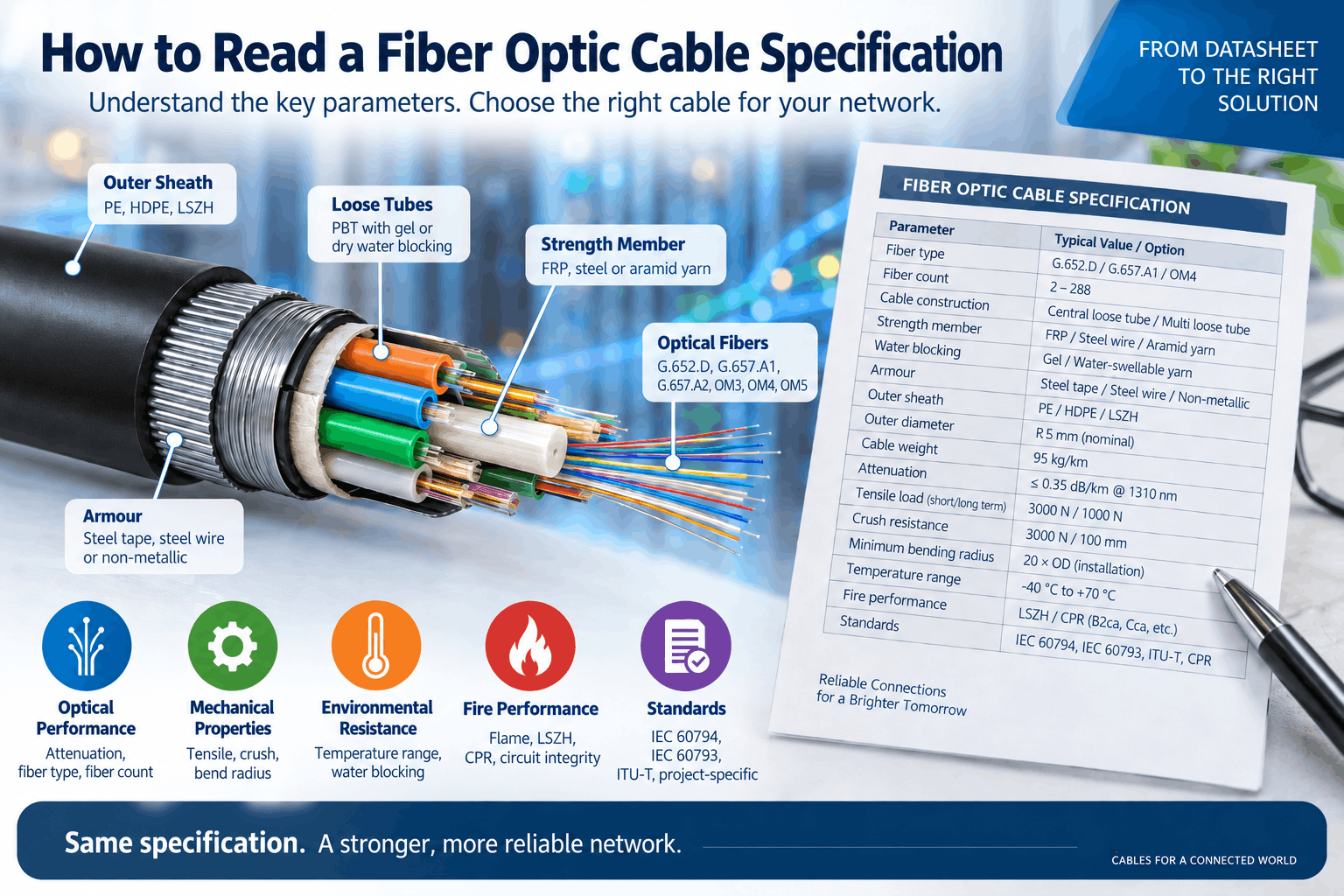
How to Read a Fiber Optic Cable Specification
Reading Time: 19 minutes
A fiber optic cable specification can contain dozens of technical parameters covering the optical fiber, cable construction, mechanical performance, environmental resistance, fire behaviour and installation limits. Understanding these values is essential when comparing cables for telecom networks, data centers, FTTH systems, railway projects, industrial infrastructure and other optical networks.
However, a datasheet should not be read as a collection of independent numbers. Fiber type affects optical performance. Cable construction affects mechanical behaviour. Installation method influences tensile and crush requirements. Meanwhile, the sheath, armour and water-blocking system determine whether the cable is appropriate for the intended environment.
For example, two 24-fiber cables can use exactly the same G.652.D optical fiber while having completely different applications. One could be a lightweight microduct cable designed for air blowing. Another could use corrugated steel tape for direct-burial mechanical protection.
Therefore, the correct way to read a fiber optic cable datasheet is to start with the application and then work through fiber type, fiber count, cable construction, optical performance, mechanical ratings, environmental limits and standards.
Quick answer: When reading a fiber optic cable specification, first identify the fiber type and count. Next, examine the cable construction, loose-tube arrangement, strength members, armour, water blocking and outer sheath. Then verify attenuation, tensile strength, crush resistance, bending radius, temperature range and cable dimensions. Finally, confirm the applicable IEC, ITU-T, CPR and project-specific requirements.
Fiber Optic Cable Specification at a Glance
| Specification Area | Typical Information | Why It Matters |
|---|---|---|
| Fiber type | G.652.D, G.657.A1, G.657.A2, OM3, OM4, OM5 | Defines optical transmission characteristics |
| Fiber count | 2, 4, 12, 24, 48, 96, 144, 288 etc. | Defines available optical pathways |
| Cable construction | Central loose tube, multi loose tube, tight buffered | Influences application and handling |
| Strength member | FRP, steel wire, aramid yarn | Provides tensile reinforcement |
| Water blocking | Gel, water-swellable yarn, water-blocking tape | Protects outdoor cable against longitudinal water penetration |
| Armour | Steel tape, steel wire, non-metallic reinforcement | Provides mechanical protection |
| Outer sheath | PE, HDPE, LSZH | Matches environmental and fire requirements |
| Attenuation | dB/km | Defines optical signal loss |
| Tensile load | N | Defines allowable pulling or operating load |
| Crush resistance | N per specified test length | Indicates resistance to compressive loading |
| Bending radius | Multiple of cable diameter or stated radius | Protects cable and fibers from excessive bending |
| Temperature | Installation, operation and storage ranges | Defines environmental limits |
| Standards | IEC 60794, IEC 60793, ITU-T, CPR etc. | Defines test and performance framework |
Consequently, no single value determines whether a fiber optic cable is suitable. The complete specification must be evaluated as one engineered system.
Start with the Cable Application
Before analysing technical values, identify where and how the cable will be installed.
Typical fiber optic cable applications include:
- Indoor installation
- Outdoor telecom networks
- Underground ducts
- Microduct systems
- Direct burial
- Aerial installation
- FTTH networks
- Data centers
- Industrial plants
- Railway and metro networks
- Tunnels
- Critical fire-resistant communication systems
A specification that looks excellent for one environment may be unsuitable for another.
For example, a very compact microduct cable can provide excellent blowing performance but may not provide the mechanical protection required for direct burial.
Therefore, always interpret the datasheet in the context of the intended installation.
Fiber Type in a Fiber Optic Cable Specification
The optical fiber designation is one of the first parameters to check.
Single-mode cables can commonly contain fibers such as:
- G.652.D
- G.657.A1
- G.657.A2
Multimode cables can commonly use:
- OM1
- OM2
- OM3
- OM4
- OM5
The fiber type determines important optical characteristics and influences where the cable can be used.
Therefore, fiber designation should never be treated as simply another product code.
G.652.D in a Fiber Optic Cable Specification
G.652.D is one of the most widely used single-mode fiber types in telecommunications infrastructure.
The current ITU-T G.652 recommendation defines geometrical, mechanical and transmission characteristics for this single-mode fiber family. G.652 fiber was originally optimized around the 1310 nm region and can also operate in the 1550 nm region.
G.652.D is widely applicable to:
- Telecom backbone networks
- Outdoor distribution networks
- Duct cables
- Direct-burial cables
- Aerial networks
- Long-distance optical links
Therefore, seeing G.652.D on a datasheet tells you about the fiber itself, but not whether the complete cable is suitable for aerial, duct or buried installation.
G.657.A1 and G.657.A2 Explained
G.657 fiber provides improved resistance to macrobending loss compared with conventional G.652 fiber.
G.657.A1 and G.657.A2 are particularly relevant to:
- FTTH networks
- Building distribution
- Subscriber drops
- Compact closures
- High-density fiber management
- Data center applications
G.657.A2 provides stronger bending performance than G.657.A1.
However, the presence of G.657.A2 does not mean that the entire cable can be bent to the same radius as the bare fiber. The finished cable still has its own minimum bending radius.
Consequently, both fiber bending characteristics and cable bending limits should be checked.
Single-Mode vs Multimode Designations
A specification may use terms such as OS2, OM3, OM4 or OM5.
These terms should be interpreted according to the network application.
Single-mode fiber is widely used for telecom, FTTH, metro, long-distance and high-capacity infrastructure.
Meanwhile, multimode fibers are commonly used for shorter-distance enterprise and data center links.
Therefore, the fiber category should match the optical transceivers, link length, wavelength and network architecture.
Fiber Count in a Fiber Optic Cable Specification
The fiber count states the number of individual optical fibers contained inside the cable.
Typical counts include:
- 2 fibers
- 4 fibers
- 6 fibers
- 8 fibers
- 12 fibers
- 24 fibers
- 48 fibers
- 72 fibers
- 96 fibers
- 144 fibers
- 288 fibers
- Higher counts for specialized networks
Importantly, fiber count is not tube count.
A 48-fiber cable does not necessarily contain 48 loose tubes. Instead, multiple fibers are commonly placed inside each tube.
For example, a 48-fiber cable could contain four tubes with twelve fibers per tube, although the exact construction depends on the manufacturer and cable design.
Fiber Count vs Number of Loose Tubes
This distinction is essential when reading a cable specification.
A datasheet may state:
- Fiber count: 96
- Number of active loose tubes: 8
- Fibers per tube: 12
In that example:
8 tubes × 12 fibers = 96 fibers.
However, some cable designs can include filler elements in addition to active fiber tubes.
Therefore, the total number of stranded elements around the central strength member may be greater than the number of fiber-containing tubes.
Why Fiber Count Does Not Determine Cable Diameter Alone
Two cables containing the same number of fibers can have very different outside diameters.
The difference can result from:
- Tube diameter
- Fiber density
- Strength-member design
- Water-blocking materials
- Armour
- Inner sheath
- Outer sheath thickness
For example, a 96-fiber microduct cable can be substantially smaller than a heavily armored 96-fiber direct-burial cable.
Consequently, fiber count should never be used as a substitute for actual cable-diameter information.
Central Loose Tube Construction
A central loose-tube cable places the optical fibers inside one principal tube positioned near the center of the cable.
This construction can provide:
- Compact diameter
- Low weight
- Simple construction
- Efficient low-to-medium fiber counts
Strength elements can then surround or accompany the central tube.
Therefore, central loose-tube construction can be attractive where compact dimensions are important.
Multi Loose Tube Construction
A multi loose-tube cable contains several tubes stranded around a central strength member.
Each tube can contain multiple optical fibers.
This design can provide:
- High fiber counts
- Organized fiber grouping
- Flexible tube allocation
- Convenient branching
- Mid-span access options
Consequently, multi loose-tube construction is widely used in feeder, backbone and distribution networks.
Central Loose Tube vs Multi Loose Tube
A datasheet should not be judged by assuming that one architecture is always superior.
Central loose tube can provide exceptional compactness.
Multi loose tube can provide greater organization at higher fiber counts.
Therefore, the correct choice depends on fiber count, route design, branching requirements and installation environment.
This is why the central loose tube vs multi loose tube fiber optic cable comparison should be considered before selecting purely by outside diameter.
What Does PBT Loose Tube Mean?
PBT stands for polybutylene terephthalate.
It is widely used for loose tubes in optical cable construction because it can provide suitable mechanical and dimensional characteristics while protecting fibers inside the cable.
The loose tube creates space around the optical fibers rather than bonding directly to them.
As a result, the fibers can remain relatively isolated from certain mechanical stresses applied to the complete cable.
How to Read Tight-Buffered Cable Construction
Tight-buffered cable places an additional protective buffer directly around individual optical fibers.
This differs from loose-tube construction, where fibers remain relatively free inside a larger tube.
Tight-buffered designs are commonly found in:
- Indoor cabling
- Data centers
- Building networks
- Patch and distribution applications
- Industrial indoor systems
Therefore, the tight-buffered vs loose-tube fiber cable distinction provides an immediate clue about the intended cable environment.
How to Read the Central Strength Member
Multi loose-tube cables frequently contain a central strength member.
Common materials include:
- FRP
- Steel
- Other reinforced composite materials
The central strength member helps the cable withstand tensile forces and maintain structural stability.
FRP also allows the cable to remain dielectric when no other metallic components are present.
Therefore, the material should be checked when an all-dielectric construction is required.
What Does FRP Mean?
FRP generally refers to Fiber Reinforced Plastic.
In optical cables, FRP is commonly used as a dielectric strength member.
Advantages can include:
- No electrical conductivity
- High tensile strength relative to weight
- Corrosion resistance
- Compatibility with non-metallic cable designs
However, an FRP central member does not automatically make the entire cable non-metallic. Steel armour, metallic moisture barriers or other metal elements can still be present.
Aramid Yarn in a Fiber Optic Cable Specification
Aramid yarn provides tensile reinforcement in many optical cable designs.
It is commonly used in:
- ADSS cables
- Indoor fiber cables
- Tight-buffered cables
- Drop cables
- Specialized non-metallic constructions
The yarn helps transfer tensile loading away from the optical fibers.
Consequently, aramid quantity and placement can significantly affect tensile performance even when the material is not visually obvious from the outside.
Glass Yarn and Rodent Protection
Glass yarn can serve several roles depending on cable construction.
It can contribute to:
- Tensile reinforcement
- Non-metallic mechanical protection
- Rodent deterrence
However, not every glass-yarn construction provides the same level of rodent protection.
Therefore, if rodent resistance is a project requirement, the datasheet or specification should state the intended protection rather than assuming that any glass layer is sufficient.
How to Read Water-Blocking Construction
Water-blocking information is particularly important for outdoor cables.
A specification can describe:
- Gel-filled loose tubes
- Thixotropic filling compound
- Water-swellable yarn
- Water-blocking tape
- Dry-core construction
- Hybrid water blocking
These systems are intended to limit longitudinal water movement through the cable.
Therefore, a project engineer should check both the construction description and the applicable finished-cable water-penetration test.
Dry Core vs Gel-Filled Cable
Dry-core cable uses water-swellable materials to limit water migration without filling large cable spaces with traditional gel.
Gel-filled construction uses suitable water-blocking compounds in defined cable areas.
Dry designs can simplify cable preparation and cleaning.
Meanwhile, gel-based systems remain widely used for outdoor telecommunications networks.
Consequently, the dry core vs gel-filled fiber optic cable decision should depend on installation practice and required environmental performance rather than assuming one technology is universally better.
What Does Armored Fiber Optic Cable Mean?
Armour adds mechanical protection around the optical cable core.
Possible constructions include:
- Corrugated steel tape
- Steel wire armour
- Steel wire braid
- Non-metallic reinforcement
Armour can improve resistance to crush, impact, rodents or direct-burial risks depending on the design.
However, armouring also increases cable diameter, weight and stiffness.
Therefore, an armored cable should be selected because the route requires mechanical protection, not simply because it appears more robust.
Corrugated Steel Tape Armour
Corrugated steel tape creates a metallic protective layer around the cable core.
It can provide strong mechanical and rodent protection while maintaining a relatively compact structure.
This type of construction is frequently encountered in outdoor and buried optical cables.
However, it introduces metallic content and changes cable flexibility.
Therefore, the corrugated steel tape vs steel wire armored fiber optic cable decision should reflect the expected mechanical loads.
Steel Wire Armored Fiber Optic Cable
Steel wire armour uses individual steel wires around the cable.
Depending on the design, it can provide significant:
- Tensile strength
- Crush protection
- Mechanical durability
- Protection for severe installation conditions
However, SWA generally increases cable size and weight more significantly than lighter armour systems.
Consequently, the datasheet’s tensile and crush values are more useful than simply comparing the word “armored.”
Metallic vs Non-Metallic Cable Construction
A fiber optic cable specification may describe the cable as:
- Metallic
- Non-metallic
- All-dielectric
All-dielectric construction can be important near electrical infrastructure because it eliminates a continuous metallic conductive path.
However, non-metallic cables still require sufficient tensile and mechanical performance for the intended environment.
Therefore, non-metallic vs metallic armored fiber optic cable selection is an engineering decision rather than simply a preference for one material.
How to Read the Outer Sheath Material
The outer sheath protects the cable from its surrounding environment.
Common descriptions include:
- PE
- HDPE
- LSZH
- Special project-specific compounds
Outdoor polyethylene jackets can provide strong resistance to moisture and environmental exposure.
Meanwhile, LSZH constructions are commonly selected indoors and in infrastructure projects requiring low-smoke and halogen-free materials.
Therefore, sheath selection should reflect installation environment and fire requirements.
Does a Black Sheath Mean Outdoor Cable?
Not necessarily.
Black polyethylene is extremely common on outdoor fiber optic cables because carbon-black-containing compounds can provide UV resistance.
However, sheath colour alone does not define the cable’s complete environmental suitability.
The specification should still confirm:
- UV resistance
- Sheath material
- Temperature range
- Water protection
- Mechanical performance
Consequently, product identification should never rely only on appearance.
Cable Diameter in a Fiber Optic Cable Specification
Outside diameter is usually stated in millimetres.
For example:
Nominal cable diameter: 10.5 mm
The word “nominal” is important because manufactured cable dimensions normally include an allowable tolerance.
Outside diameter affects:
- Duct fill
- Microduct compatibility
- Cable glands
- Closures
- Drum capacity
- Bending radius
- Installation handling
Therefore, diameter is an important engineering parameter rather than simply a packaging detail.
How to Read Cable Weight
Fiber optic cable weight is commonly stated as kilograms per kilometre.
For example:
95 kg/km
Cable weight affects:
- Drum handling
- Aerial loading
- Installation force
- Transportation
- Support requirements
Armoured cables generally weigh more than comparable dielectric designs.
Consequently, cable weight should be considered together with tensile strength rather than in isolation.
How to Read Attenuation in a Fiber Optic Cable Specification
Attenuation describes optical signal loss as light travels through the fiber.
It is commonly expressed as:
dB/km
A single-mode specification can provide maximum attenuation values at wavelengths such as:
- 1310 nm
- 1383 nm
- 1550 nm
- 1625 nm
The precise wavelengths depend on fiber type and specification.
Lower attenuation means less optical power is lost for a given distance.
Therefore, attenuation directly influences optical link budgeting.
Maximum vs Typical Attenuation
This distinction is important when comparing datasheets.
A maximum value represents the manufacturer’s declared upper limit under the stated specification.
A typical value describes performance commonly observed in production but may not represent the guaranteed acceptance limit.
Consequently, procurement comparisons should preferably compare guaranteed maximum values with other guaranteed maximum values.
Comparing one supplier’s typical attenuation with another supplier’s maximum attenuation can produce a misleading conclusion.
What Does dB/km Mean?
dB/km expresses optical attenuation per kilometre.
For a simplified example, if fiber attenuation were 0.35 dB/km at a given wavelength, ten kilometres of fiber would contribute approximately 3.5 dB of fiber attenuation before splice, connector and other system losses are added.
Therefore, the complete optical power budget includes more than cable attenuation alone.
Splices, connectors, splitters and other optical components can add additional losses.
Tensile Strength in a Fiber Optic Cable Specification
Tensile performance describes the cable’s ability to withstand longitudinal pulling forces.
Datasheets commonly distinguish between:
- Installation tensile load
- Short-term tensile load
- Long-term tensile load
- Operating tensile load
The exact terminology varies between specifications.
Values are generally expressed in newtons.
Therefore, always check whether a stated tensile value represents temporary installation loading or continuous service conditions.
Short-Term vs Long-Term Tensile Load
A cable can often withstand a higher tensile force during a controlled installation period than during continuous operation.
For example, an aerial cable may experience permanent mechanical tension after installation.
Consequently, its long-term load requirement is particularly important.
Meanwhile, a duct cable may experience its maximum tensile load primarily during pulling.
Therefore, the route and installation method determine which tensile parameter deserves the greatest attention.
How to Read Crush Resistance
Crush resistance describes how the cable performs when subjected to compressive force.
This is important in environments such as:
- Underground installations
- Cable trays
- Direct burial
- Industrial routes
- Congested ducts
Crush values should always be interpreted together with the specified test method and loaded length.
Consequently, simply comparing two numbers without checking test conditions can be misleading.
Impact Resistance
Impact testing evaluates cable behaviour under localized mechanical impact.
This differs from crush testing, which applies a defined compressive force.
Armour, sheath thickness and cable-core construction can all influence impact performance.
Therefore, direct-burial and industrial applications can place greater emphasis on impact performance than protected indoor installations.
Bending Radius in a Fiber Optic Cable Specification
Every finished fiber optic cable has a minimum allowable bending radius.
Datasheets can express this as:
- A specific radius in millimetres
- A multiple of the cable outside diameter
For example, a specification might define different limits for:
- During installation
- After installation
The installation radius can be larger because the cable can simultaneously experience tension.
Therefore, both values should be checked before routing the cable.
Fiber Bend Radius vs Cable Bend Radius
These are not the same parameter.
A G.657.A2 optical fiber has strong macrobending performance, but the complete cable surrounding that fiber includes:
- Tubes
- Strength elements
- Sheaths
- Armour where applicable
Consequently, the complete cable can require a much larger bending radius than the optical fiber itself.
Always follow the finished-cable specification during installation.
Temperature Limits in a Fiber Optic Cable Specification
Fiber optic cable datasheets commonly define several temperature ranges.
These can include:
- Operating temperature
- Installation temperature
- Storage temperature
- Transportation temperature
They should not automatically be assumed to be identical.
For example, a cable may operate at a low temperature after installation but require a warmer minimum temperature during installation because polymer flexibility changes with temperature.
Therefore, installation crews should use the installation range rather than the operating range when planning cable pulling.
How to Read Cable Installation Type
A datasheet can describe installation as:
- Duct
- Microduct
- Direct burial
- Aerial
- Indoor
- Indoor/outdoor
- Tray
- Conduit
These terms are not interchangeable.
A duct fiber optic cable benefits from external protection provided by the duct.
A direct burial fiber optic cable, by contrast, must withstand a harsher mechanical environment without that continuous protective pathway.
Consequently, identical optical specifications do not make the two constructions equivalent.
How to Read Microduct Cable Specifications
A microduct cable specification places particular emphasis on:
- Small outside diameter
- Low weight
- Suitable stiffness
- Low-friction outer surface
- Tensile performance
- Blowing compatibility
The relationship between cable diameter and microduct internal diameter is important, but it is not the only factor affecting installation performance.
Route length, bends, friction and blowing equipment also matter.
Therefore, microduct fiber optic cable selection should consider the complete installation system.
How to Read ADSS Cable Specifications
ADSS stands for All-Dielectric Self-Supporting.
These cables are designed for aerial installation without a separate metallic supporting messenger.
Important ADSS parameters can include:
- Span length
- Maximum allowable tension
- Everyday tension
- Sag
- Wind loading
- Ice loading where relevant
- Aramid reinforcement
- Outer sheath characteristics
Therefore, ADSS fiber optic cable should never be selected only by fiber count and diameter.
How to Read Direct-Burial Cable Specifications
Direct-burial cable operates without continuous external duct protection.
Therefore, the specification may include additional:
- Armour
- Rodent protection
- Water blocking
- Crush resistance
- Impact resistance
- Durable PE sheath
However, not every direct-burial cable uses metallic armour.
Non-metallic mechanical protection can also be designed for suitable applications.
How to Read Aerial Cable Specifications
Aerial optical cables must support mechanical loads over spans between attachment points.
Possible constructions include:
- ADSS
- Messenger-supported cables
- Figure-8 cables
- Specialized aerial drop cables
Important parameters can include span, tension, sag and environmental loading.
Consequently, the word “aerial” alone is not sufficient to define the cable.
How to Read FTTH Drop Cable Specifications
FTTH drop cables usually contain a relatively small number of fibers.
Common parameters include:
- 1, 2 or 4 fibers
- G.657.A1 or G.657.A2 fiber
- Parallel strength elements
- Flat or round profile
- Optional aerial messenger
- LSZH or outdoor sheath material
Therefore, an FTTH fiber optic cable specification should be interpreted according to whether the product is feeder, distribution or subscriber drop cable.
How to Read Fire Performance
Fiber optic cables can also carry fire-performance classifications.
These can include:
- Flame propagation
- LSZH characteristics
- CPR Euroclass
- Smoke classification
- Acidity classification
- Circuit integrity where applicable
These terms describe different characteristics.
Consequently, a cable described as “LSZH” should not automatically be assumed to be B2ca, Cca or fire resistant.
How to Read CPR Cable Classification
A European cable datasheet may include a reaction-to-fire classification such as:
B2ca-s1a,d1,a1
The primary Euroclass can include:
- B2ca
- Cca
- Dca
- Eca
Meanwhile, supplementary classifications can describe smoke, flaming droplets and acidity.
Therefore, the complete designation provides more information than the primary class alone.
Our CPR cable classes comparison explains these ratings in greater detail.
LSZH Does Not Mean Fire Resistant
This is one of the most common datasheet interpretation mistakes.
LSZH describes low-smoke and halogen-free material characteristics.
Fire resistance or circuit integrity describes whether a cable can maintain its function during fire under a defined test.
Therefore:
LSZH ≠ circuit integrity.
Likewise, LSZH alone does not define a CPR Euroclass.
How to Read IEC 60794 References
The IEC 60794 family is one of the most important international standard frameworks for optical fiber cables.
IEC 60794-1-1 provides generic requirements covering areas such as:
- Geometry
- Transmission
- Materials
- Mechanical properties
- Environmental ageing
- Climatic behaviour
Meanwhile, other IEC 60794 parts address particular cable applications and test methods.
Therefore, a specification stating only “IEC 60794” can be less informative than one identifying the relevant part and project requirements.
IEC 60794-3 for Outdoor Fiber Optic Cable
IEC 60794-3 applies to optical fiber cables intended for external communication networks.
The current 2022 edition covers cable applications including:
- Duct installation
- Direct burial
- Aerial installation
- Lake and river crossings
- Certain specialized infrastructure environments
Consequently, IEC 60794-3 is particularly relevant when interpreting outdoor cable specifications.
IEC 60793 and Optical Fiber Specifications
IEC 60793 focuses on optical fibers rather than the complete cable construction.
For example, the current IEC 60793-2-50:2025 applies to class B single-mode fibers and includes categories corresponding to fiber families such as:
- B-652
- B-653
- B-654
- B-655
- B-656
- B-657
Therefore, IEC 60793 and IEC 60794 should not be confused.
One primarily defines optical-fiber requirements, while the other provides specifications and test frameworks for complete optical cables and cable elements.
ITU-T vs IEC Fiber Designations
Telecom datasheets frequently use ITU-T fiber names such as G.652.D and G.657.A2.
IEC specifications use their own fiber-category framework.
The standards are coordinated, and IEC 60793-2-50 provides mappings between relevant IEC and ITU-T single-mode fiber categories.
Consequently, seeing a different naming convention does not necessarily mean the fibers are unrelated.
However, procurement specifications should use clearly defined standards to avoid ambiguity.
How to Read Cable Marking Requirements
Cable specifications often define information that must be printed on the outer sheath.
Typical marking can include:
- Manufacturer
- Product designation
- Fiber count
- Fiber type
- Relevant standard
- Production year
- Length marking
- Batch identification
- CPR information where applicable
However, marking requirements differ by project and market.
Therefore, the exact sheath legend should be agreed before production when customers require project-specific wording.
How to Read Drum Length
Fiber optic cables are commonly supplied on drums in defined manufacturing lengths.
Typical drum lengths can vary significantly according to:
- Cable diameter
- Cable weight
- Drum dimensions
- Route design
- Customer requirement
Longer continuous lengths can reduce the number of field joints.
However, excessively large drums can create transport and handling problems.
Consequently, drum length should be coordinated with the actual project route.
Nominal Values vs Guaranteed Values
A technical datasheet can contain several types of numbers.
These may be described as:
- Nominal
- Typical
- Maximum
- Minimum
- Tolerance
These terms have different meanings.
A nominal diameter is a design target rather than an absolute manufactured dimension.
A maximum attenuation value can represent a guaranteed limit.
A typical performance value may represent normal production performance without being the contractual maximum.
Therefore, buyers should distinguish guaranteed acceptance criteria from descriptive engineering values.
How to Compare Two Fiber Optic Cable Specifications
When comparing suppliers, use an identical sequence for every datasheet.
First compare:
- Fiber type
- Fiber count
- Fibers per tube
- Cable architecture
Next compare:
- Strength members
- Water blocking
- Armour
- Sheath material
Then compare:
- Outside diameter
- Weight
- Tensile rating
- Crush resistance
- Bending radius
- Temperature limits
Finally, compare optical limits, standards and certification.
As a result, price comparisons can be made between technically equivalent constructions rather than products that merely have the same fiber count.
Common Fiber Optic Cable Specification Mistakes
1. Selecting Only by Fiber Count
Two 48-fiber cables can have completely different construction and performance.
2. Confusing Fiber Count with Tube Count
Multiple optical fibers are commonly installed inside each loose tube.
3. Comparing Typical Values with Maximum Values
This can create a misleading supplier comparison.
4. Ignoring the Fiber Type
G.652.D, G.657.A1, G.657.A2 and multimode fibers have different intended characteristics.
5. Assuming G.657 Defines the Cable Bend Radius
The finished cable has separate mechanical bending limits.
6. Assuming FRP Means the Cable Is Completely Non-Metallic
Other metallic layers can still be present.
7. Selecting Armour Without Considering Mechanical Values
Actual tensile, crush and impact performance is more informative than the word “armored.”
8. Assuming PE Means Direct Burial
An outdoor polyethylene sheath alone does not prove that the cable is designed for direct burial.
9. Assuming Black Means Outdoor
Sheath colour is not a complete environmental specification.
10. Ignoring Water Blocking
Outdoor ducts and underground routes can contain significant moisture.
11. Confusing Operating and Installation Temperature
A cable can have different limits for each condition.
12. Ignoring Long-Term Tensile Load
This is particularly important for aerial cables.
13. Comparing Crush Values Without Test Conditions
The numerical value must be interpreted with the applicable method and loaded length.
14. Assuming LSZH Means B2ca
Material description and CPR classification are separate.
15. Assuming Flame Retardant Means Fire Resistant
Flame propagation and circuit integrity measure different fire characteristics.
16. Reading Only the Product Name
Similar commercial names can hide significantly different constructions.
17. Ignoring Standard Editions
Standards can be revised over time, so the applicable edition should be verified for major projects.
18. Ignoring Drum Length
Short manufacturing lengths can increase the required number of field joints.
19. Choosing the Smallest Cable Without Checking Strength
High fiber density is useful only if mechanical requirements remain satisfied.
20. Assuming the Highest Specification Is Always Best
Unnecessary armour, fire performance or tensile strength can increase diameter, weight and cost without adding value to the actual route.
How to Read a Fiber Optic Cable Specification Step by Step
Step 1: Identify the Application
Determine whether the cable will be installed indoors, outdoors, in duct, microduct, direct burial or aerially.
Step 2: Check Fiber Type
Confirm G.652.D, G.657.A1, G.657.A2, OM3, OM4, OM5 or another specified fiber.
Step 3: Check Fiber Count
Confirm current capacity together with future spare-fiber requirements.
Step 4: Examine Tube Architecture
Identify central loose tube, multi loose tube, tight buffered or another design.
Step 5: Check Strength Members
Identify FRP, steel, aramid or other reinforcement.
Step 6: Review Water Blocking
Determine whether the cable uses gel, dry water-blocking materials or a hybrid construction.
Step 7: Review Mechanical Protection
Check steel tape, SWA, glass yarn or other protection according to route risk.
Step 8: Check Outer Sheath
Verify PE, HDPE, LSZH or another project-specific material.
Step 9: Review Optical Performance
Compare maximum attenuation values at the relevant wavelengths.
Step 10: Review Mechanical Ratings
Check tensile load, crush resistance, impact performance and minimum bending radius.
Step 11: Review Temperature Limits
Verify installation, operation and storage temperature ranges.
Step 12: Review Fire Performance
Check flame, LSZH, CPR and circuit-integrity requirements where applicable.
Step 13: Verify Standards
Confirm the applicable IEC, ITU-T, national and project-specific standards.
Step 14: Check Drum Length and Marking
Confirm manufacturing length and customer-specific sheath-printing requirements.
Step 15: Compare Equivalent Specifications
Only compare commercial offers after confirming that the proposed constructions satisfy the same technical requirements.
What Should Buyers Include in a Fiber Optic Cable RFQ?
A well-prepared RFQ allows the manufacturer to select the correct construction without unnecessary assumptions.
Useful information includes:
- Application
- Installation method
- Fiber count
- Fiber type
- Single-mode or multimode requirement
- Central loose tube or multi loose tube where specified
- Fibers per tube where specified
- Strength-member requirement
- All-dielectric requirement
- Water-blocking requirement
- Armour requirement
- Rodent protection
- Outer sheath material
- Maximum outside diameter where relevant
- Maximum cable weight where relevant
- Installation tensile load
- Operating tensile load
- Crush resistance
- Impact requirement
- Minimum bending radius
- Installation temperature
- Operating temperature
- Attenuation limits
- Required wavelengths
- IEC standards
- ITU-T fiber requirement
- CPR class where applicable
- LSZH requirement where applicable
- Fire-survival requirement where applicable
- Cable marking
- Drum length
- Required test documentation
- Project or end-user specification
Consequently, suppliers can quote technically comparable cables and procurement teams can evaluate offers more accurately.
ETK Kablo Fiber Optic Cable Specifications
ETK Kablo manufactures fiber optic cables across a broad range of telecom, data, infrastructure and industrial applications.
Available constructions include central loose-tube, multi loose-tube, microduct, armored, non-metallic armored, aerial, ADSS, tight-buffered, indoor, outdoor and fire-performance fiber optic cables.
Depending on the cable family, ETK can manufacture products using single-mode fibers such as G.652.D, G.657.A1 and G.657.A2 together with multimode fiber options including OM1 through OM5.
Fiber counts can be selected according to the specific cable family and network requirements, including high-count telecommunications constructions for backbone and distribution infrastructure.
Meanwhile, mechanical design can be adapted through FRP, aramid yarn, glass yarn, corrugated steel tape, steel wire or other project-specific protective systems.
Water blocking can use dry, gel-filled or combined technologies according to cable design and installation environment.
Therefore, an ETK fiber optic cable specification should always be evaluated as a complete construction rather than identifying the product only through fiber type and fiber count.
Frequently Asked Questions About Fiber Optic Cable Specifications
What information is included in a fiber optic cable specification?
A specification typically includes fiber type, fiber count, cable construction, materials, dimensions, optical performance, mechanical ratings, temperature limits, fire characteristics and applicable standards.
What does G.652.D mean on a fiber cable datasheet?
G.652.D identifies a widely used single-mode optical fiber category defined through ITU-T requirements.
What does G.657.A2 mean?
G.657.A2 identifies bend-insensitive single-mode fiber with stronger macrobending performance than G.657.A1.
Does 48-core cable contain 48 tubes?
No. Fiber count describes individual optical fibers. Multiple fibers are normally grouped inside each loose tube.
What does 12 fibers per tube mean?
It means that each active loose tube contains twelve optical fibers.
What does FRP mean in fiber optic cable?
FRP means Fiber Reinforced Plastic and is commonly used as a dielectric strength member.
What does PBT mean?
PBT means polybutylene terephthalate and is widely used for loose tubes in optical cable construction.
What does dB/km mean?
It expresses optical attenuation, or signal loss, per kilometre of optical fiber.
Is lower fiber attenuation better?
Lower attenuation reduces optical signal loss, although the complete network power budget also includes connectors, splices, splitters and other components.
What is nominal cable diameter?
It is the specified design diameter of the cable, normally subject to manufacturing tolerance.
What does kg/km mean?
It describes the approximate cable weight in kilograms for each kilometre of cable.
What does tensile load mean?
Tensile load defines the longitudinal pulling or operating force the cable can withstand under specified conditions.
What does crush resistance mean?
It describes how the cable withstands compressive loading under a defined test method.
What is minimum bending radius?
It is the smallest permitted radius through which the finished cable should be bent under the specified installation or operating condition.
Is fiber bending radius the same as cable bending radius?
No. The finished cable contains tubes, strength elements, sheaths and potentially armour, so its bending limit differs from that of the individual fiber.
What is dry-core fiber optic cable?
Dry-core cable uses water-swellable materials to restrict longitudinal water migration without filling major cable spaces with conventional gel.
What does armored fiber optic cable mean?
It means the cable includes additional mechanical protection such as corrugated steel tape, steel wire or another protective construction.
Does PE sheath mean direct burial?
No. PE is an outer-sheath material. Direct-burial suitability depends on the complete cable construction and mechanical performance.
Does LSZH mean fire resistant?
No. LSZH relates to smoke and halogen characteristics. Circuit integrity requires separate fire-survival performance.
What does IEC 60794 mean?
IEC 60794 is a family of international standards covering optical fiber cables, including generic, application-specific and test requirements.
What is the difference between IEC 60793 and IEC 60794?
IEC 60793 primarily concerns optical fibers, while IEC 60794 concerns complete optical fiber cables and cable elements.
How should two fiber optic cable datasheets be compared?
Compare fiber type, count, construction, strength members, water blocking, armour, sheath, dimensions, optical values, mechanical performance, temperature limits and standards using equivalent acceptance criteria.
Conclusion
Reading a fiber optic cable specification correctly requires much more than checking fiber count and attenuation.
The optical fiber designation establishes important transmission characteristics. However, the cable construction determines how those fibers are protected during manufacturing, installation and long-term operation.
Central loose-tube, multi loose-tube and tight-buffered constructions serve different network requirements. Likewise, FRP, aramid yarn, glass yarn, steel tape and steel wire provide different approaches to structural reinforcement and mechanical protection.
Water blocking, armour and outer-sheath materials should then be matched to the actual installation environment.
Read the Complete Specification Before Comparing Cables
Mechanical values are equally important. Tensile load determines how much longitudinal force the cable can tolerate, while crush and impact ratings indicate resistance to external mechanical loads. Bending radius protects both the structural cable elements and the optical fibers.
Meanwhile, attenuation defines optical signal loss, but guaranteed maximum values should be distinguished from typical production values when comparing suppliers.
Finally, standards provide the framework for evaluating performance. IEC 60793 describes optical-fiber requirements, while the IEC 60794 family addresses optical cable construction and performance. ITU-T recommendations such as G.652 and G.657 define important telecom fiber characteristics.
Therefore, the best purchasing decision comes from comparing complete, technically equivalent cable specifications rather than selecting the lowest price, smallest diameter or highest mechanical rating in isolation.
A correctly interpreted datasheet ultimately answers one question: Is this exact cable construction suitable for the network, environment and installation method in which it will actually operate?
Benzer yazılar
JZ vs OZ Control Cable: What Do the Core Identification Codes Mean?
JZ vs OZ control cable is a common comparison when specifying flexible multicore cables for industrial machinery, control panels, autom...
Ethernet Cable Testing: NEXT, Return Loss, Insertion Loss and ACR Explained
Ethernet cable testing verifies whether a twisted-pair copper cabling system can transmit data within the electrical performance limits...

Fiber Optic Cable Attenuation: 850, 1310, 1550 and 1625 nm Explained
Fiber optic cable attenuation describes the reduction in optical power as light travels through an optical fiber. It is normally expres...
A-02YSF(L)2Y vs A-2Y(L)2Y Outdoor Telephone Cable
A-02YSF(L)2Y vs A-2Y(L)2Y is an important comparison when selecting copper outdoor telephone cable for telecommunications networks, und...
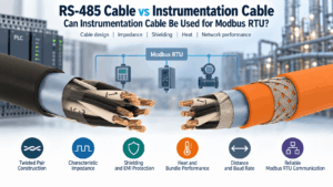
RS-485 Cable vs Instrumentation Cable: Can Instrumentation Cable Be Used for Modbus RTU?
A Modbus RTU cable must do more than carry a low-voltage digital signal from one device to another. Modbus RTU commonly uses an RS-485 ...
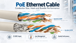
Ethernet Cable for PoE: Conductor Size, Heat and Bundle Performance
A PoE Ethernet cable carries data and electrical power over the same balanced twisted-pair cabling system. This capability simplifies t...
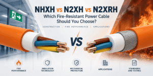
NHXH vs N2XH vs N2XRH: Which Fire-Resistant Power Cable Should You Choose?
NHXH vs N2XH vs N2XRH is an important comparison when specifying 0.6/1 kV power cables for emergency and life-safety systems. Although ...

How to Specify Low Current Cables for Infrastructure Projects
A professional low current cable specification should define much more than a cable name, conductor count or sheath colour. Infrastruct...
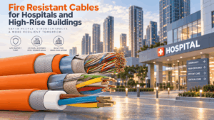
Fire Resistant Cables for Hospitals and High-Rise Buildings
Fire resistant cable for hospitals and high-rise buildings supports electrical, communication and control systems that may need to rema...

Industrial Control Cable Selection for Automation and Machinery
Industrial control cable selection should begin with the function of the circuit and the mechanical conditions of the machine rather th...
FE180 Fiber Optic Cable: Fire Integrity, Applications and Selection
An FE180 fiber optic cable is designed for optical communication routes where continued transmission during fire can form part of the p...

Screened vs Unscreened Control Cable: What Is the Difference?
Control cable shielding is one of the most important design decisions when selecting cable for industrial automation, machinery, buildi...


