





 President’s Message
Blog
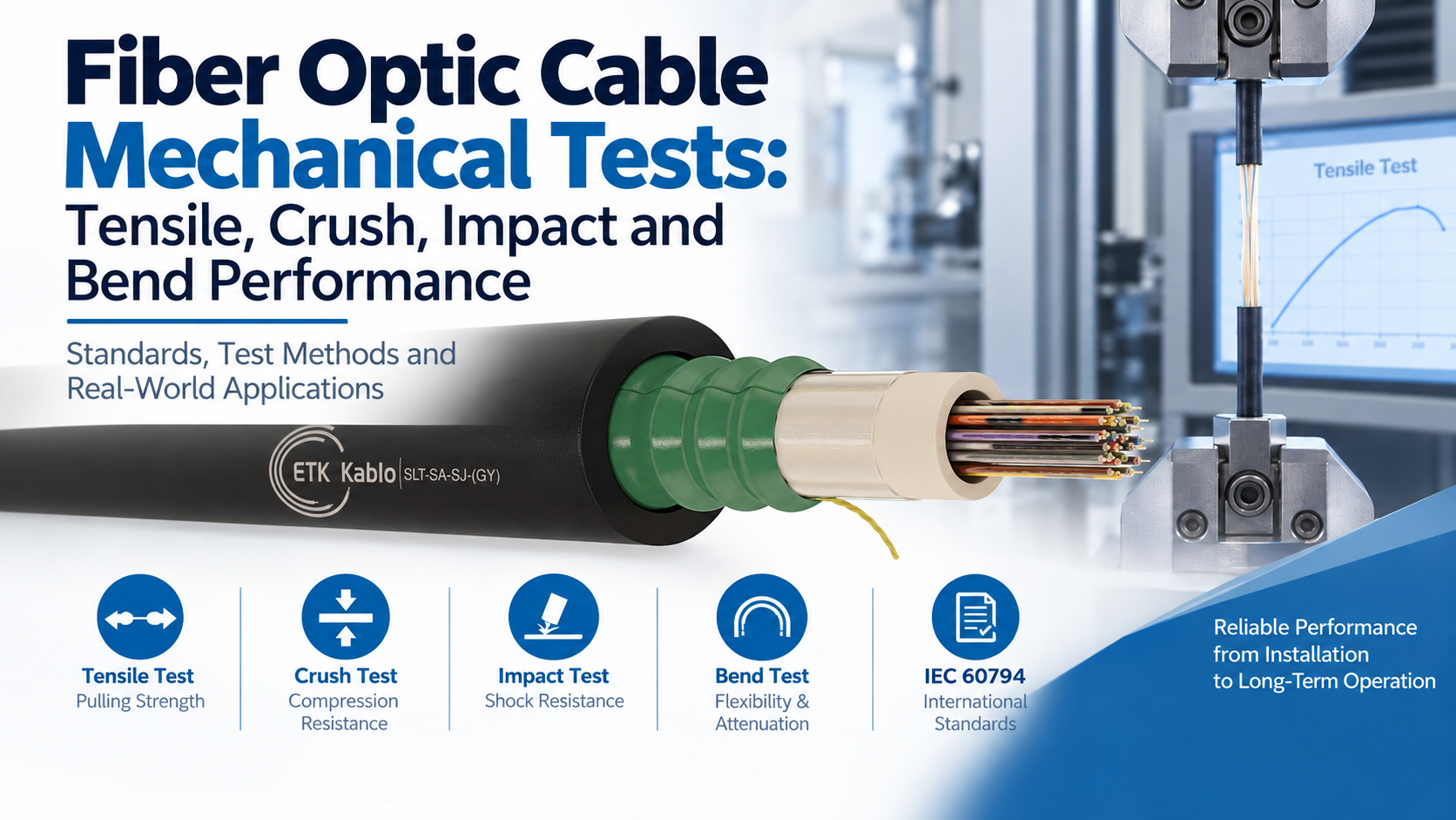
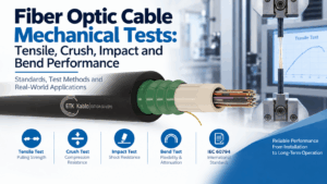
Fiber Optic Cable Mechanical Tests: Tensile, Crush, Impact and Bend Performance
Reading Time: 18 minutes
Fiber optic cable testing is essential because good optical performance alone does not prove that a cable can survive installation and long-term service. Outdoor, underground, aerial, industrial and railway fiber optic cables can experience pulling forces, crushing pressure, impact, bending, torsion and other mechanical stresses before they ever begin carrying network traffic.
A cable can show excellent attenuation on a drum and still fail in the field if its internal fibers experience excessive strain during pulling, if loose tubes deform under crushing pressure or if the cable is bent below its permitted radius.
For this reason, mechanical qualification forms a major part of the IEC 60794 optical cable test framework. Tensile, crush, impact and bend tests simulate different mechanical stresses and evaluate whether the cable protects the optical fibers while maintaining acceptable transmission performance.
However, the highest tensile or crush figure does not automatically identify the “best” fiber optic cable. Required performance depends on the application. A lightweight indoor cable, an underground duct cable, an armored direct-burial cable and an ADSS aerial cable face very different mechanical demands.
Quick answer: the tensile test measures how the cable behaves under longitudinal pulling force. The crush test applies compression across a defined cable length. The impact test evaluates resistance to localized mechanical shock, while the bend test checks whether the cable can withstand controlled bending without excessive attenuation or physical damage. Engineers should compare the test method, applied load, duration and acceptance criteria rather than compare one isolated mechanical number.
Fiber Optic Cable Testing at a Glance
| Mechanical Test | Primary Stress | Typical Result Format | Main Purpose |
|---|---|---|---|
| Tensile | Longitudinal pulling force | N | Simulates installation and operating tension |
| Crush | Transverse compression | N / defined length | Evaluates resistance to squeezing and compression |
| Impact | Localized mechanical shock | J or Nm | Simulates sudden external impact |
| Bend | Controlled curvature | Mandrel radius or multiple of cable diameter | Evaluates attenuation and damage during bending |
| Repeated bending | Cyclic bending | Cycles, radius and applied load | Evaluates durability under repeated movement |
| Torsion | Twisting | Angle and cycles | Evaluates resistance to rotational stress |
Consequently, mechanical performance should be treated as a collection of different characteristics rather than one universal strength rating.
What Is Fiber Optic Cable Testing?
Fiber optic cable testing includes procedures used to verify optical, mechanical, environmental and material performance.
Mechanical tests focus on whether the complete cable can protect the fibers against forces that occur during:
- Manufacturing
- Drum handling
- Transportation
- Cable pulling
- Duct installation
- Direct burial
- Aerial installation
- Operation
- Maintenance
The cable structure must transfer those external loads through strength members, tubes, armour, fillers and jacket materials without placing unacceptable stress on the optical fibers.
Therefore, mechanical qualification evaluates the complete cable design rather than the glass fiber alone.
Why Fiber Optic Cable Testing Matters
Optical fiber has extremely high tensile strength under ideal conditions, but practical telecommunications fibers are very small glass structures whose transmission performance can change when they experience excessive strain, bending or localized pressure.
For this reason, a fiber optic cable is engineered as a mechanical protection system around the optical fibers.
Typical protective elements can include:
- Loose tubes
- Tight buffers
- Aramid yarn
- Glass yarn
- FRP strength members
- Steel strength members
- Corrugated steel tape
- Steel wire armour
- Polyethylene outer jackets
- LSZH outer jackets
Each element performs a different role in controlling the forces that ultimately reach the fiber.
Mechanical Strength vs Optical Performance
Fiber optic cable mechanical testing is unusual because the pass/fail criterion can involve both mechanical integrity and optical transmission.
A cable may look physically undamaged after a test but still experience unacceptable attenuation change.
Likewise, temporary attenuation can occur under load and disappear once the stress is removed.
Therefore, mechanical qualification can evaluate:
- Attenuation during the test
- Attenuation after the test
- Fiber strain
- Permanent deformation
- Jacket damage
- Tube damage
- Armour damage
- Fiber breakage
The exact acceptance criteria depend on the cable specification and application.
IEC 60794 and Fiber Optic Cable Testing
The IEC 60794 series provides the principal international framework for optical fiber cable construction and testing.
IEC 60794-1-2 provides general guidance and a reference structure for optical cable test methods.
Mechanical procedures have historically been identified by the letter E.
Important examples include:
- E1 – Tensile
- E3 – Crush
- E4 – Impact
- E6 – Repeated bending
- E7 – Torsion
- E10 – Kink
- E11 – Bend
- E17 – Bending stiffness
The IEC structure is evolving, and individual mechanical procedures are increasingly published as separate IEC 60794-1-1xx standards rather than remaining only inside one consolidated mechanical-test document.
Therefore, engineers can encounter both older and newer standard references on fiber optic cable datasheets.
Why Older Datasheets Use IEC 60794-1-2-E1 or E3
Many existing manufacturer datasheets use references such as:
- IEC 60794-1-2-E1
- IEC 60794-1-2-E3
- IEC 60794-1-2-E4
- IEC 60794-1-2-E11
These references reflect an earlier organization of the IEC optical cable test framework.
Later editions placed mechanical methods within IEC 60794-1-21, while the newest IEC structure progressively separates individual tests into dedicated documents.
Consequently, two datasheets can describe essentially the same mechanical test using different generations of standard numbering.
The test method itself should therefore be understood before assuming the documents describe different performance requirements.
Fiber Optic Cable Testing: Tensile Performance
The tensile test is one of the most important forms of fiber optic cable testing.
It evaluates the cable’s ability to withstand longitudinal force.
This force occurs most obviously when installers pull cable through ducts, conduits or cable trays.
Aerial cables can also remain under tensile load after installation.
The tensile test therefore helps answer two separate questions:
- How much force can the cable tolerate during installation?
- How much continuous load can it tolerate during service?
IEC Tensile Test Method E1
The IEC tensile procedure is identified as Method E1.
The current standalone tensile test document is IEC 60794-1-101.
During the test, a defined length of cable is subjected to a specified tensile force.
Optical performance can be monitored while the load is applied.
Depending on the specification, the test can evaluate:
- Fiber strain
- Attenuation change
- Cable elongation
- Physical damage
Therefore, the test measures more than the force required to physically break the cable.
Maximum Installation Tension
Maximum installation tension represents the temporary pulling force that the cable can tolerate during installation.
This value is especially important in:
- Long duct routes
- Conduit installations
- Underground networks
- Large infrastructure projects
- Cable installations involving several bends
Pulling tension can increase because of friction between the cable and duct walls.
Therefore, route design, lubricant, pulling equipment and bend geometry can influence the actual mechanical load.
Maximum Operating Tension
Operating tension is different from installation tension.
Installation force is typically temporary.
Operating tension can remain on the cable for long periods.
Consequently, the permitted operating tension is usually lower than the short-term installation value.
Continuous load must not create long-term fiber strain or optical degradation.
Why Fiber Strain Matters During Tensile Testing
One purpose of the cable structure is to prevent tensile force from transferring directly to the optical fibers.
Loose-tube cable designs can provide excess fiber length inside the tubes.
As the overall cable extends slightly under tension, the internal fibers can remain relatively unstressed until the available excess length is consumed.
Strength members should carry most of the mechanical load.
Therefore, fiber strain represents a particularly useful parameter when evaluating tensile performance.
How Strength Members Improve Tensile Performance
Fiber optic cables can use several types of longitudinal strength members.
Common examples include:
- Aramid yarn
- Glass yarn
- FRP rods
- Steel wires
- Steel messenger wires
Aramid yarn provides high tensile strength at relatively low weight.
FRP can provide strong non-metallic reinforcement.
Steel provides very high mechanical strength but adds metallic content and weight.
Consequently, required tensile performance strongly influences cable construction.
Tensile Strength and Cable Weight
Some fiber cable specifications express required tensile load partly as a function of cable weight.
This approach becomes useful in aerial and heavy outdoor constructions where the cable’s own mass contributes to mechanical loading.
However, cable weight alone should not be used to compare products.
A mechanically optimized lightweight cable can provide high tensile strength through efficient strength-member design.
Fiber Optic Cable Testing: Crush Performance
The crush test evaluates resistance to transverse compressive force.
Instead of pulling the cable along its length, the test compresses a section of the cable from the side.
This type of stress can occur when:
- Cables are stacked
- Heavy cables press against smaller cables
- Backfill applies local pressure
- Cable trays become overloaded
- A cable is trapped against a hard surface
- Construction equipment applies pressure
Therefore, crush performance is especially important for underground and mechanically exposed installations.
Understanding Crush Resistance in N/100 mm
Crush resistance is commonly stated as a force over a defined cable length.
For example:
3000 N / 100 mm
This does not mean that the entire cable can support only 3000 N.
It means that the standardized test applies the specified transverse compression across the defined test section.
Therefore, N and N/100 mm should never be treated as interchangeable mechanical specifications.
What the Crush Test Evaluates
During crushing, internal cable components can deform.
Potential effects include:
- Loose-tube flattening
- Fiber microbending
- Jacket deformation
- Armour deformation
- Changes in pair geometry in hybrid cables
- Temporary attenuation increase
A well-designed cable distributes the external load while protecting the fibers from excessive localized pressure.
Consequently, optical monitoring provides important information during the crush test.
Crush Strength vs Armour
Armour can improve mechanical protection, but the relationship is not always straightforward.
Corrugated steel tape can provide strong circumferential protection against crushing and impact.
Steel wire armour can provide high mechanical strength and can also contribute significantly to tensile performance.
Non-metallic reinforcement can protect the cable while maintaining a dielectric construction.
Therefore, armour type should be selected according to the actual mechanical risks rather than by assuming all armored cables perform identically.
Fiber Optic Cable Testing: Impact Performance
The impact test evaluates how the cable responds to a sudden localized mechanical shock.
This differs from crush testing.
Crush applies compression over a defined area for a specified period.
Impact applies mechanical energy rapidly.
Possible real-world impact sources include:
- Dropped tools
- Construction debris
- Accidental blows
- Installation equipment
- Handling damage
Therefore, a cable can have strong crush performance yet still require separate impact qualification.
IEC Impact Test Method E4
Impact testing is identified as Method E4.
The current standalone IEC document is IEC 60794-1-104.
The procedure subjects the cable to controlled impact energy using defined test equipment.
Depending on the specification, engineers can evaluate:
- Attenuation change
- Visible jacket damage
- Internal component damage
- Fiber breakage
- Performance after repeated impacts
Consequently, the energy value should always be read together with the number of impacts and acceptance criteria.
Understanding Impact Ratings in Nm or Joules
Mechanical impact energy can be expressed in joules or newton metres.
For energy, 1 J is dimensionally equivalent to 1 Nm.
However, a statement such as “10 Nm impact” does not provide the complete test definition.
Important accompanying information can include:
- Number of impacts
- Striker geometry
- Test position
- Cable support
- Measured optical change
Therefore, engineers should compare complete test conditions rather than only the headline energy value.
Crush vs Impact: What Is the Difference?
| Characteristic | Crush Test | Impact Test |
|---|---|---|
| Load type | Compression | Sudden mechanical shock |
| Application | Gradual or sustained squeezing | Localized strike |
| Typical unit | N / defined length | J or Nm |
| Main risk | Core deformation and microbending | Localized physical damage |
| Same test? | No | No |
Consequently, specifying only crush strength does not establish impact resistance, and vice versa.
Fiber Optic Cable Testing: Bend Performance
Bending is one of the most important mechanical conditions affecting optical cable performance.
Every installation requires cable to pass through bends, trays, ducts, cabinets or jointing areas.
If the bend becomes too tight, optical fibers can experience increased curvature.
This can cause:
- Macrobending loss
- Microbending effects
- Tube deformation
- Jacket damage
- Permanent cable distortion
Therefore, bend testing evaluates both optical and mechanical behaviour.
IEC Bend Test Method E11
The cable bend test is identified as Method E11.
The current dedicated IEC document is IEC 60794-1-111.
The procedure bends the fiber optic cable around a defined test mandrel.
The primary objective is to evaluate attenuation change while the cable undergoes controlled bending.
The procedure can also evaluate physical cable damage.
Consequently, bend performance cannot be reduced to visual inspection alone.
Bend Test vs Minimum Bending Radius
The standardized bend test and the published minimum bending radius are related but not identical concepts.
The bend test describes a laboratory qualification procedure.
Minimum bending radius provides an installation or service limitation for the finished cable.
A datasheet might state:
- Fixed installation: 15 × cable diameter
- During installation or operation: 20 × cable diameter
These values instruct designers and installers how tightly the cable may be routed.
Therefore, a cable that successfully passes an E11 laboratory test still needs to be installed within its published bend-radius limits.
What Does 20 × D Mean?
The letter D normally represents the outside diameter of the cable.
For a cable with a 12 mm outer diameter:
20 × D = 240 mm bending radius.
For a 20 mm cable:
20 × D = 400 mm bending radius.
Therefore, the same multiple produces a larger physical bend radius as cable diameter increases.
Why Tight Bends Increase Optical Attenuation
Optical transmission depends on light remaining confined within the fiber core.
Excessive curvature can change propagation conditions sufficiently for some optical power to escape.
This phenomenon is commonly associated with macrobending loss.
Therefore, a tight cable route can increase attenuation even when the fiber itself has not physically broken.
Bend-insensitive fibers such as G.657.A1 and G.657.A2 can reduce sensitivity at the fiber level, but the complete cable still has mechanical bend limits.
Repeated Bending Test
A single bend and repeated bending represent different mechanical conditions.
Some installations experience movement during handling or operation.
The repeated bending test cyclically bends the cable under defined conditions.
The objective is to determine whether repeated mechanical movement causes:
- Jacket fatigue
- Strength-member damage
- Loose-tube damage
- Fiber damage
- Attenuation increase
Therefore, repeated bending provides additional information beyond one static bend event.
Repeated Bending Does Not Mean Drag-Chain Approval
This distinction is particularly important.
Passing an IEC repeated-bending cable test does not automatically mean that the cable is designed for millions of continuous flex cycles in a robotic drag chain.
Dynamic industrial cables require specialized construction and endurance qualification.
Consequently, ordinary telecom fiber optic cable should not be described as continuous-flex cable solely because it passes a repeated bending test.
Fiber Optic Cable Bending Stiffness
Bending stiffness measures how strongly a cable resists being curved.
This characteristic influences:
- Installation handling
- Routing effort
- Drum behaviour
- Cable-tray placement
- Minimum practical routing space
The IEC 60794 family now includes a dedicated bending-stiffness method.
However, stiffness and minimum bend radius should not be confused.
A cable can be mechanically stiff yet still have a defined permissible bending radius established by the manufacturer.
Kink Resistance and Fiber Optic Cables
A kink represents a much more severe local deformation than an ordinary bend.
Kinking can occur when cable forms a loop and that loop is pulled tight during installation.
This creates extremely concentrated curvature.
Consequently, kinking can damage:
- Loose tubes
- Strength members
- Fibers
- Armour
- Outer jacket
Installers should therefore prevent cable loops from tightening during pulling even when the cable has passed formal mechanical qualification tests.
Torsion and Fiber Optic Cable Testing
Fiber optic cables can also experience twisting during installation.
A cable coming incorrectly off a drum can accumulate torsion.
The torsion test evaluates how the cable responds when one end is rotated relative to the other.
Excessive torsion can disturb internal cable geometry and increase fiber stress.
Therefore, torsion testing complements tensile, crush, impact and bend qualification.
Why Attenuation Is Monitored During Mechanical Tests
One of the major advantages of optical mechanical testing is the ability to monitor transmission performance while stress is applied.
Mechanical pressure can produce microbending or macrobending before visible physical damage develops.
As a result, attenuation can act as an early indicator of internal stress.
Depending on the test specification, acceptance can require:
- Attenuation increase below a defined limit
- No permanent attenuation increase after unloading
- No fiber break
- No unacceptable fiber strain
- No physical damage
Therefore, a complete mechanical test report should include optical as well as mechanical observations where required.
Temporary vs Permanent Attenuation Change
A cable can experience a temporary attenuation increase while under mechanical load.
Once the force is removed, the cable structure can recover and attenuation can return close to its original level.
Another cable can retain elevated attenuation after the test.
That difference is important.
Permanent optical change can indicate that the mechanical stress altered the internal fiber or cable structure.
Consequently, test specifications often distinguish performance during loading from performance after recovery.
Why Test Wavelength Matters
Mechanical deformation can affect attenuation differently depending on wavelength.
Longer optical wavelengths can be particularly sensitive to bending effects.
Therefore, the applicable test specification can define the wavelength or wavelengths used during optical monitoring.
For single-mode systems, test wavelengths can include commonly used transmission windows such as 1310 nm and 1550 nm.
However, engineers should follow the exact standard and product specification rather than assume one universal monitoring wavelength.
Fiber Optic Cable Testing and Loose-Tube Construction
Loose-tube outdoor cable is specifically engineered to isolate fibers from external mechanical stress.
The fibers have controlled excess length inside the tube.
This design can provide several advantages during tensile, bending and temperature changes.
When the cable stretches slightly, the fibers can remain relatively unstressed within the available geometric margin.
Therefore, tube geometry and excess fiber length are critical mechanical design parameters.
Central Loose Tube vs Multi Loose Tube Mechanical Performance
Central loose-tube and multi loose-tube cables distribute mechanical loads differently.
A central tube contains fibers within one central protective element.
A multi loose-tube design strands several fiber tubes around a central strength member.
The multi-tube architecture can support high fiber counts and provides considerable design flexibility for armour and strength elements.
However, neither architecture is automatically mechanically stronger.
Actual performance depends on the complete cable construction.
Tight-Buffered Fiber and Mechanical Tests
Tight-buffered cables hold buffer material more closely around the optical fiber.
This architecture provides convenient handling and termination for indoor and equipment applications.
However, mechanical forces transfer differently compared with loose-tube cable.
Therefore, tight-buffered cables must be tested according to their own design and intended environment rather than compared directly with heavy outdoor loose-tube products.
Fiber Optic Cable Armour and Mechanical Performance
Armour is one of the most visible construction features associated with mechanical protection.
Different armour systems can include:
- Corrugated steel tape
- Steel wire
- Steel wire braid
- Non-metallic armour
- Glass yarn reinforcement
These constructions can influence tensile, crush and impact behaviour differently.
Therefore, armour selection should correspond to the dominant mechanical risk.
Corrugated Steel Tape and Crush Protection
Corrugated steel tape forms a metallic layer around the cable core.
The corrugation provides flexibility while maintaining strong circumferential protection.
This construction can provide useful resistance against:
- Crushing
- Impact
- Rodent attack
- Mechanical handling damage
Consequently, corrugated steel tape is common in outdoor and underground fiber optic cable designs.
Steel Wire Armour and Tensile Performance
Steel wires can provide substantial longitudinal mechanical strength.
This makes steel wire construction attractive where the cable faces high pulling or tensile loads.
Depending on geometry, the wires can also improve resistance to other mechanical stresses.
However, steel wire increases cable weight and metallic content.
Therefore, the strongest steel-armored cable is not automatically appropriate for every duct or data-network application.
Non-Metallic Armoured Fiber and Mechanical Tests
Non-metallic cable constructions use materials such as FRP and glass yarn to provide mechanical reinforcement without conductive metallic armour.
This can be useful where projects require:
- Dielectric construction
- Electrical isolation
- Reduced lightning concerns
- Lower weight
- Strong tensile reinforcement
Nevertheless, non-metallic does not mean mechanically weak.
The actual tensile and crush figures should determine performance.
Fiber Optic Cable Testing for Duct Applications
Duct installation creates significant tensile demands because installers pull cable through long routes.
Bends increase friction and therefore pulling tension.
Crush can also occur at rollers, ducts, chambers or cable-contact points.
Consequently, important mechanical parameters for duct cable include:
- Maximum installation tension
- Bending radius
- Crush resistance
- Impact resistance
- Outer-sheath durability
Therefore, duct-cable selection should not rely only on fiber count and outside diameter.
Fiber Optic Cable Testing for Direct Burial
Direct-burial cable faces more uncontrolled mechanical conditions than protected duct cable.
Potential stresses include:
- Soil pressure
- Rocks
- Backfill
- Ground movement
- Construction activity
- Rodents
For this reason, crush and impact performance can become especially important.
Mechanical protection such as armour can provide additional reliability.
Fiber Optic Cable Testing for Aerial Applications
Aerial cables experience a different mechanical environment.
Long-term tensile load can result from:
- Cable weight
- Span length
- Wind
- Ice loading
- Temperature change
ADSS and messenger-supported fiber cables therefore require mechanical engineering beyond ordinary underground cable requirements.
Tensile strength becomes particularly important.
However, bending, torsion and installation tension must still remain within specified limits.
Fiber Optic Cable Testing for Railway and Infrastructure Projects
Large infrastructure projects often expose fiber cables to demanding installation and operating conditions.
Railway, airport, tunnel and industrial networks can involve:
- Long cable pulls
- Congested cable trays
- Mechanical vibration
- Restricted bend space
- Outdoor sections
- Underground sections
Therefore, project specifications can require more detailed mechanical performance documentation than ordinary building installations.
Indoor vs Outdoor Fiber Optic Mechanical Performance
An indoor cable does not necessarily need the same crush or tensile capability as a heavy outdoor cable.
Indoor design often prioritizes:
- Low smoke and halogen-free materials
- Flame performance
- Compact dimensions
- Flexibility
- Ease of termination
Outdoor cable can prioritize:
- Pulling strength
- Crush resistance
- Impact resistance
- Water blocking
- UV resistance
- Armour
Consequently, mechanical numbers should always be interpreted within the intended application.
How to Read Fiber Optic Cable Testing Data
A professional fiber cable datasheet normally presents more information than a single pass/fail statement.
For each mechanical test, review:
- Test standard
- Method number
- Applied force or energy
- Duration
- Number of cycles or impacts
- Bend radius where applicable
- Attenuation criterion
- Fiber-strain criterion
- Physical-damage criterion
Therefore, two products should only be compared after confirming that their test conditions are equivalent.
Why 3000 N and 3000 N/100 mm Are Completely Different
This is one of the most important datasheet-reading distinctions.
3000 N tensile strength describes longitudinal pulling force.
3000 N/100 mm crush resistance describes transverse compression over a specified cable length.
The identical number does not mean that the performances are equivalent.
Therefore, units must always be interpreted together with the test type.
Mechanical Test Values Are Not Universal Requirements
There is no single tensile, crush or impact value that every fiber optic cable should meet.
A lightweight indoor cable can be perfectly suitable with lower mechanical ratings than a steel-armored outdoor cable.
Likewise, microduct fiber cable can prioritize low diameter and blowing performance rather than extremely high armour strength.
Therefore, mechanical qualification should follow the intended installation.
Common Fiber Optic Cable Testing Mistakes
Choosing Cable Only by Tensile Strength
High pulling strength does not establish crush, impact or bend performance.
Assuming Armored Means Mechanically Superior in Every Test
Different armour types improve different mechanical characteristics.
Comparing N With N/100 mm
Tensile force and crush force use fundamentally different test configurations.
Ignoring Installation Tension vs Operating Tension
Short-term pulling force and long-term permissible load are separate limits.
Ignoring Optical Attenuation During Testing
A cable can look intact while internal fiber stress increases optical loss.
Ignoring Fiber Strain
Tensile load should be transferred primarily through the strength members rather than the optical fibers.
Assuming Bend Radius Is the Same as Bend Test
Bend radius is an installation constraint, while E11 defines a standardized laboratory test procedure.
Assuming Repeated Bending Means Continuous Flex
Ordinary telecom cable is not automatically suitable for robotic drag chains.
Ignoring Cable Diameter When Reading Bend Radius
A 20 × D limit produces different physical radii for different cable diameters.
Comparing Test Results Without Checking Duration
A load applied for seconds and a load maintained for many minutes can represent different stress conditions.
Ignoring the Number of Impacts
Impact energy must be interpreted together with repetitions and test geometry.
Assuming Zero Visible Damage Means the Test Passed
Optical attenuation or fiber strain can exceed acceptance limits without obvious exterior damage.
Using Laboratory Limits as Installation Targets
Installation should include an engineering safety margin rather than intentionally operating at the qualification limit.
How to Specify Fiber Optic Cable Testing Requirements
Define the Installation Environment
Start by identifying indoor, outdoor, duct, direct-burial, aerial or other installation conditions.
Specify Maximum Installation Tension
Ensure that the cable can tolerate the expected pulling loads with appropriate margin.
Specify Long-Term Operating Tension
For installations where continuous tension exists, define the permissible sustained load.
Define Crush Resistance
State the required load, test length and acceptance criteria rather than writing only “crush resistant.”
Define Impact Performance
Specify impact energy and applicable IEC method where mechanical shock is relevant.
Define Bend Performance
Include minimum permitted bend radius and applicable mechanical qualification method.
Review Repeated Bending
Where cable can experience movement, confirm whether cyclic bend testing is necessary.
Review Torsion
Long pulls, drum handling and equipment installations can justify torsion requirements.
Set Optical Acceptance Criteria
Define the permitted attenuation change during and after mechanical loading.
Set Fiber-Strain Limits
For tensile testing, specify maximum permitted fiber strain where required.
Require Physical Inspection
Confirm that tubes, jacket, armour and fibers show no unacceptable damage after testing.
Check the Exact IEC Method
Use the applicable IEC 60794 mechanical method rather than a generic statement such as “tested according to IEC.”
Fiber Optic Cable Testing RFQ Checklist
A professional fiber optic cable testing requirement can include:
- Fiber type
- Fiber count
- Cable construction
- Loose tube or tight buffer
- Installation application
- Maximum installation tension
- Maximum operating tension
- Fiber-strain limit
- Crush resistance
- Crush test duration
- Impact energy
- Number of impacts
- Bending radius
- Bend test requirements
- Repeated bending requirements
- Torsion requirements
- Kink requirement where applicable
- Permitted attenuation change
- Test wavelength
- Armour requirement
- Water-blocking requirement
- Operating temperature
- Installation temperature
- Applicable IEC 60794 method
- Required laboratory test report
Consequently, manufacturers can evaluate the complete mechanical requirement rather than respond only to fiber count and cable designation.
ETK Kablo Fiber Optic Cable Testing
ETK Kablo manufactures indoor, outdoor, armored, non-metallic, duct, aerial, fire-resistant and project-specific fiber optic cable constructions.
Mechanical qualification forms an important part of ETK fiber optic cable design and laboratory testing.
Depending on the product, ETK technical data can include:
- Maximum installation tension
- Maximum operating tension
- Fiber-strain acceptance criteria
- Crush strength
- Impact resistance
- Torsion
- Repeated bending
- Bending performance
- Temperature cycling
- Water penetration
For example, ETK outdoor multi loose-tube constructions can specify installation tensions in the kilonewton range together with crush resistance measured over 100 mm cable sections.
Armored and reinforced constructions can be engineered for still higher mechanical requirements depending on the project.
Therefore, ETK can match fiber optic cable testing requirements with the actual cable architecture instead of applying one mechanical specification to every fiber optic cable family.
Example: ETK Outdoor Dry Multi Loose Tube Cable
One ETK A-DQ(ZN)2Y outdoor dry multi loose-tube construction provides a useful example of how mechanical values appear on a professional datasheet.
Its published mechanical test data includes:
- Minimum installation tension in the kilonewton range
- Separate lower long-term operating tension
- Crush resistance specified in N/100 mm
- Defined impact energy and number of impacts
- Torsion cycles
- Repeated bending qualification
- Controlled bend testing
The tensile acceptance criteria also distinguish fiber strain under installation load from attenuation performance under operating load.
This illustrates why one mechanical number cannot describe complete cable performance.
Example: ETK Reinforced Fiber Optic Cable
Reinforced ETK constructions demonstrate how mechanical requirements change with cable design.
Some steel-reinforced outdoor fiber cables provide installation tensile ratings significantly above ordinary lightweight designs.
Other constructions are optimized for high crush resistance.
Therefore, reinforcement should be selected according to the project requirement rather than simply added to maximize every mechanical figure.
Frequently Asked Questions About Fiber Optic Cable Mechanical Tests
What mechanical tests are performed on fiber optic cable?
Common tests include tensile, crush, impact, bend, repeated bending, torsion, kink and bending-stiffness tests.
What is a fiber optic cable tensile test?
It applies longitudinal force to determine whether the cable can withstand installation or operating tension without excessive fiber strain, attenuation change or damage.
What is the IEC tensile test method?
The IEC mechanical tensile procedure is Method E1, with the current dedicated test document published as IEC 60794-1-101.
What is crush resistance in fiber optic cable?
It describes the cable’s ability to withstand transverse compressive load over a defined test section without unacceptable optical or physical damage.
What does 3000 N/100 mm mean?
It means the standardized crush test applies 3000 N of transverse force over the specified 100 mm cable section under the defined test conditions.
What is the fiber optic cable impact test?
It applies controlled mechanical impact energy to evaluate resistance to sudden localized shocks.
What is Method E4?
E4 is the IEC impact test method for optical fiber cables.
What is a bend test?
It bends the cable around a defined mandrel and evaluates attenuation change and possible physical damage.
What is IEC Method E11?
It is the optical fiber cable bend test method, now covered by IEC 60794-1-111.
What does 20 × D bending radius mean?
It means the minimum radius equals twenty times the outside diameter of the cable.
Is bending radius the same as bending diameter?
No. Radius measures from the centre of the bend to the cable path. Bending diameter is twice the radius.
Why does fiber attenuation increase when cable bends?
Excessive curvature can cause optical power to escape from the guided mode and can also create mechanical stress or microbending.
Does G.657 fiber eliminate bend-radius requirements?
No. Bend-insensitive fiber improves fiber-level performance, but the complete cable still has mechanical bend limits.
What is repeated bending?
It cyclically bends a cable under defined conditions to evaluate mechanical fatigue and optical performance.
Does repeated bending mean a cable is drag-chain rated?
No. Continuous-flex robotics applications require purpose-designed dynamic cable and appropriate endurance testing.
What is maximum installation tension?
It is the maximum short-term tensile load permitted while installing the cable.
What is maximum operating tension?
It is the lower sustained tensile load that the cable can tolerate during normal service under the specified conditions.
Why is fiber strain measured during tensile testing?
Excessive strain indicates that too much tensile force is reaching the optical fibers rather than being carried by the cable strength members.
Is armored fiber optic cable always stronger?
Armour normally improves certain mechanical characteristics, but different armour systems affect tensile, crush and impact performance differently.
What mechanical test is most important for underground cable?
Tensile, crush, impact and bend performance can all be important. The relative priority depends on whether the cable is ducted, directly buried or otherwise mechanically protected.
What mechanical test is most important for aerial fiber cable?
Tensile performance is particularly important because aerial cables can remain under continuous longitudinal load, although bend and torsion requirements also matter.
Can two fiber cables with the same fiber count have different mechanical performance?
Yes. Strength members, loose-tube design, armour, jacket, cable diameter and other construction features can produce very different mechanical ratings.
How should fiber optic mechanical test results be compared?
Compare the same test method, units, applied force or energy, duration, number of cycles and optical acceptance criteria.
Conclusion
Fiber optic cable testing provides the evidence that a cable can protect its optical fibers during installation and long-term service.
Tensile testing evaluates longitudinal pulling and operating loads. Crush testing measures resistance to transverse compression, while impact testing evaluates sudden localized mechanical shocks.
Bend testing addresses one of the most critical optical-mechanical interactions because excessive curvature can increase attenuation even before visible cable damage develops.
However, these tests should never be interpreted independently from the cable’s intended application.
A lightweight indoor cable, duct cable, direct-burial cable, ADSS cable and steel-armored fiber optic cable do not need identical mechanical values.
Compare the Test Method, Not Just the Number
First, identify the mechanical stresses expected during installation and operation.
Next, specify tensile, crush, impact and bend requirements using the relevant IEC 60794 test procedures.
Afterward, review optical acceptance criteria such as attenuation change and fiber strain.
Finally, compare complete test conditions, including units, duration, cycles and cable construction.
Ultimately, the strongest fiber optic cable is not the product with the largest number on one mechanical test. The correct cable is the construction that provides the mechanical protection required by the actual route while preserving stable optical performance throughout installation and service.
Benzer yazılar
EN 45545-2 HL1 vs HL2 vs HL3: Railway Cable Fire Requirements
EN 45545-2 hazard levels define different fire-performance requirements for materials and components installed on railway vehicles. For...
0.4 mm vs 0.6 mm vs 0.8 mm Telephone Cable Conductors: How to Select
Telephone cable conductor diameter directly affects electrical resistance, transmission performance, copper content, cable size, weight...
RE-Y vs RE-2Y vs RE-2X Instrumentation Cable: PVC, PE and XLPE Insulation Compared
RE-Y vs RE-2Y vs RE-2X is fundamentally a comparison of the insulation materials surrounding the copper conductors inside an instrument...
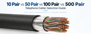
10 Pair vs 50 Pair vs 100 Pair vs 500 Pair Telephone Cable: Selection Guide
Telephone cable pair count is one of the first specifications engineers and procurement teams must define when selecting a multi-pair c...
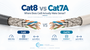
Cat8 vs Cat7A Cable: Where Does Cat8 Actually Make Sense?
Cat8 vs Cat7A is often presented as a simple comparison in which Cat8 is assumed to be the newer, faster and therefore better Ethernet ...
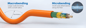
Fiber Optic Cable Bend Radius: Macrobending vs Microbending Explained
Fiber optic bend radius is one of the most important installation limits in an optical cable system. A fiber cable can meet its attenua...

Foam-Skin vs Solid PE Insulation in Telephone Cables
Foam-skin vs solid PE is an important insulation choice in outdoor copper telephone cables because the material surrounding each conduc...
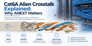
Cat6A Alien Crosstalk Explained: Why ANEXT Matters
Cat6A alien crosstalk is one of the most important performance considerations in high-speed copper structured cabling. As Ethernet freq...
Fiber Optic Cable Mechanical Tests: Tensile, Crush, Impact and Bend Performance
Fiber optic cable testing is essential because good optical performance alone does not prove that a cable can survive installation and ...
Jelly-Filled vs Dry-Core Outdoor Telephone Cable
Jelly-filled vs dry-core is an important construction choice when specifying outdoor telephone cable for telecom distribution networks,...
0.5 vs 0.75 vs 1.0 vs 1.5 mm² Control Cable: How to Select Conductor Size
Control cable conductor size affects resistance, voltage drop, current-carrying capability, cable diameter, flexibility and cost. Among...

300/500 V vs 450/750 V Control Cable: When Is the Higher Voltage Rating Required?
Control cable voltage rating is one of the most important electrical parameters to check when selecting cables for industrial machinery...


