





 President’s Message
Blog
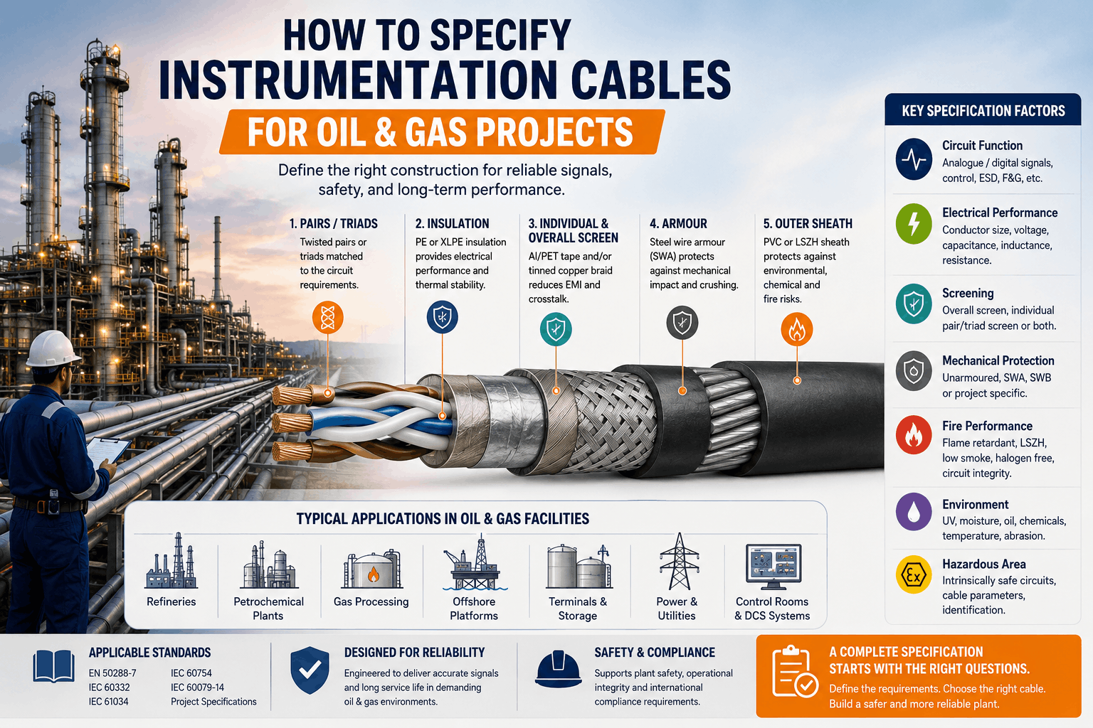
How to Specify Instrumentation Cables for Oil & Gas Projects
Reading Time: 12 minutes
Selecting oil and gas instrumentation cables requires much more than choosing a conductor size and adding a screen. Refineries, petrochemical plants, gas processing facilities, terminals and other process installations combine sensitive analogue and digital signals with electromagnetic interference, hazardous-area requirements, mechanical exposure, fire-safety criteria and demanding environmental conditions.
A technically complete cable specification must therefore define the electrical circuit, conductor configuration, screening arrangement, insulation and sheath materials, mechanical protection, fire performance, environmental exposure and applicable standards as separate requirements.
This is particularly important at the procurement stage. A request such as “instrumentation cable, 12 pair, armored” can describe several very different cable constructions. A more detailed specification allows manufacturers, EPC contractors and project engineers to compare technically equivalent offers and reduces the risk of receiving a cable that meets the basic description but not the actual conditions of the plant.
Quick answer: To specify instrumentation cables for an oil and gas project, first define the circuit and pair or triad configuration. Then determine conductor size, electrical parameters, individual or overall screening, armour requirement, insulation and sheath materials, fire performance, environmental resistance and hazardous-area considerations. Finally, reference the applicable cable standard and project-specific documentation requirements in the RFQ.
How to Select Oil and Gas Instrumentation Cables
A practical specification can be developed in a logical sequence rather than beginning with a cable code.
| Specification Step | What Must Be Defined | Why It Matters |
|---|---|---|
| 1. Circuit | Signal type and system function | Determines electrical and configuration requirements |
| 2. Elements | Pairs, triads or cores | Matches the cable to connected instruments |
| 3. Conductor | Cross-section and conductor class | Affects resistance, loop performance and mechanical properties |
| 4. Screening | Overall, individual or combined screens | Controls EMI and circuit-to-circuit interference |
| 5. Insulation | PE, XLPE or other specified material | Affects electrical, thermal and environmental performance |
| 6. Mechanical Protection | Unarmored, SWA, SWB or project-specific design | Protects the cable against physical damage |
| 7. Outer Sheath | PVC, LSZH or project-specified compound | Relates to environment and fire performance |
| 8. Fire Requirements | Flame propagation, smoke, halogen or circuit integrity | Defines safety performance separately from signal performance |
| 9. Environment | UV, moisture, chemicals, hydrocarbons and temperature | Ensures material compatibility with the installation location |
| 10. Standards | International, national and project specifications | Provides a common basis for manufacturing and testing |
Following this sequence helps prevent one of the most common procurement problems: selecting a familiar cable designation before the actual project conditions have been established.
1. Start with the Instrumentation Circuit
The first question should not be “Which cable code should we use?” It should be “What circuit will this cable serve?”
Instrumentation systems in oil and gas facilities can carry signals associated with:
- Pressure transmitters
- Flow measurement
- Level measurement
- Temperature monitoring
- Control valves
- Distributed Control Systems (DCS)
- Programmable Logic Controllers (PLC)
- Emergency Shutdown Systems (ESD)
- Fire and gas monitoring interfaces
- Other process measurement and control circuits
The characteristics of the connected equipment and loop should establish the cable requirements.
For example, a low-level analogue measurement circuit may place greater importance on electrical noise control than a simple status signal. Likewise, intrinsically safe circuits can introduce additional limitations involving cable capacitance, inductance and circuit separation.
Beginning with the actual loop therefore gives the specification an engineering basis rather than treating all instrumentation circuits as interchangeable.
2. Specify Pairs, Triads or Multicore Construction
Instrumentation cables can contain twisted pairs, twisted triads or groups of individual cores. The required arrangement depends on the circuit and the project specification.
A pair consists of two insulated conductors twisted together. Pair constructions are widely used for many analogue and digital instrumentation circuits.
A triad consists of three insulated conductors grouped and twisted together. Triads may be specified for circuits that require three conductors to be maintained as one functional element.
The correct choice should come from the instrument loop drawings, I/O schedules and project engineering documentation rather than from a general assumption that one configuration is superior.
Don’t Specify Only the Total Number of Conductors
A request for a “24-core instrumentation cable” is not necessarily equivalent to a 12-pair cable.
The pair or triad structure affects conductor grouping, twisting and screening. For projects where circuit separation and noise performance matter, this distinction should appear clearly in both the cable schedule and RFQ.
3. Define Conductor Size and Electrical Performance
Conductor cross-section is another parameter that should be selected according to circuit requirements rather than copied automatically from a previous project.
Common instrumentation cable designs may use conductor cross-sections such as:
- 0.50 mm²
- 0.75 mm²
- 1.00 mm²
- 1.50 mm²
- 2.50 mm²
The appropriate size depends on factors including circuit length, conductor resistance, voltage drop, connected equipment and project requirements.
Instrumentation specifications may also define electrical characteristics such as:
- Maximum conductor resistance
- Insulation resistance
- Mutual capacitance
- Capacitance unbalance
- Inductance or L/R characteristics where applicable
- Operating voltage
- Test voltage
These values should be reviewed against the requirements of the complete circuit rather than evaluated only as isolated cable properties.
Electrical Parameters Are Especially Important for Intrinsically Safe Circuits
Where a cable forms part of an intrinsically safe circuit, its distributed electrical characteristics can become part of the safety calculation.
The project designer may therefore need cable capacitance, inductance or inductance-to-resistance data to verify the complete loop against the permitted parameters of the connected apparatus and associated safety barrier.
For these circuits, selecting a cable solely according to conductor size and voltage rating is not sufficient.
4. Overall Screen vs Individual Pair or Triad Screens
Oil and gas facilities contain many potential sources of electromagnetic interference, including motors, variable-frequency drives, power cables, switching equipment and electrical distribution systems.
Screening helps protect low-level instrumentation signals from these disturbances.
However, there are different screening architectures.
Overall Screen
An overall screen surrounds the complete cable core.
This arrangement can provide protection against electromagnetic interference entering the cable from the surrounding environment and is widely used for general instrumentation circuits.
Individual Pair or Triad Screens
In individually screened constructions, each pair or triad receives its own metallic screen.
This can improve separation between circuits within the same cable and may be particularly valuable where multiple sensitive signals share one cable.
Designations such as PiMF and TiMF refer to individually screened pairs and triads respectively.
Individual and Overall Screening Together
Some demanding specifications combine individually screened pairs or triads with an additional overall screen.
This architecture addresses two different concerns:
- Interference between circuits inside the cable
- Electromagnetic interference coming from outside the cable
The highest level of screening is not automatically required for every loop. Screening should be selected according to signal sensitivity, circuit grouping, cable route and project EMC requirements.
5. Choose the Insulation Material According to the Project
The insulation surrounding each conductor contributes to electrical performance and influences temperature capability and environmental durability.
Instrumentation cable specifications commonly use materials such as PE or XLPE, depending on the cable design.
PE Insulation
Polyethylene provides useful electrical properties and is widely used in communication and instrumentation cable constructions.
XLPE Insulation
Cross-linked polyethylene provides strong electrical characteristics together with increased thermal and mechanical performance compared with conventional thermoplastic polyethylene constructions.
ETK’s instrumentation portfolio includes multiple designs using XLPE insulation, including overall-screened, individually screened and armored constructions.
The required insulation material should nevertheless come from the project specification. It should not be selected simply because one material appears more advanced.
6. When Is Armouring Required?
Screening and armouring perform different functions.
Screening primarily addresses electromagnetic performance.
Armouring primarily provides mechanical protection.
An instrumentation cable installed in a protected indoor tray may not require the same mechanical construction as a cable routed outdoors, underground or through an exposed process area.
Oil and gas specifications may therefore call for:
- Unarmored cables
- Steel wire armored cables (SWA)
- Steel wire braid protected cables (SWB)
- Other project-specific mechanical constructions
SWA is often considered where substantial mechanical protection is required. Steel wire braid can offer a different balance of protection and flexibility.
The correct choice depends on installation method, expected mechanical stress, bending requirements and project standards.
Armour should not be added simply because the project is in the oil and gas sector. The cable route should justify the mechanical requirement.
7. Select the Outer Sheath for the Actual Environment
The outer sheath forms the cable’s primary environmental barrier and should be specified according to where the cable will operate.
Possible project considerations include:
- Indoor or outdoor installation
- UV exposure
- Moisture
- Ambient temperature
- Oil exposure
- Hydrocarbons
- Chemical contamination
- Abrasion
- Fire and smoke requirements
PVC and halogen-free compounds are both used in instrumentation cable designs, but they should not be treated as interchangeable.
Likewise, a generic statement such as “oil and gas cable” does not automatically prove resistance to every hydrocarbon or chemical that may exist in a particular plant.
If resistance to oil, fuel, chemicals or other substances is important, the required material property and test method should be stated explicitly in the project specification.
8. Define Fire Performance Separately
Another frequent specification error is using terms such as “flame retardant,” “fire resistant” and “LSZH” as though they describe the same property.
They do not.
A project may separately require:
- Resistance to vertical flame propagation
- Reduced flame propagation in cable bunches
- Low smoke emission
- Halogen-free performance
- Low corrosivity of combustion gases
- Circuit integrity during fire
These requirements address different aspects of cable behaviour in a fire.
Common test families referenced in cable specifications include IEC 60332 for flame propagation, IEC 61034 for smoke density and IEC 60754 for halogen and acidity-related characteristics.
The exact tests and performance levels should follow the project fire strategy rather than being added automatically to every instrumentation cable.
LSZH Does Not Automatically Mean Fire Resistant
LSZH describes low-smoke, halogen-free material behaviour. It does not by itself demonstrate that a cable will continue transmitting a circuit during a fire.
If circuit integrity is required for a particular safety system, that requirement needs to be specified and verified separately.
9. Instrumentation Cables in Hazardous Areas
Oil and gas facilities frequently include locations classified because a flammable gas or vapour may be present.
However, it is important not to assume that the cable alone determines whether an electrical circuit is suitable for a hazardous area.
The complete installation must be designed according to the applicable hazardous-area protection concept, equipment certification, wiring method and installation standard.
Intrinsically Safe Circuits
Instrumentation cables are frequently used as part of intrinsically safe circuits.
In this case, cable electrical parameters can affect the permitted energy-storage characteristics of the complete loop. The designer should verify cable capacitance and inductance data against the requirements of the intrinsic-safety calculation.
The specification may also need to address:
- Separation from non-intrinsically safe circuits
- Screening and earthing arrangement
- Cable identification
- Unused conductor treatment
- Termination practices
- Applicable hazardous-area installation requirements
Does an Intrinsically Safe Circuit Require a Blue Cable?
IEC 60079-14 requires intrinsically safe circuit cabling to be identifiable. Where colour is used as the method of identification, light blue is used for intrinsically safe circuits.
However, the standard also provides circumstances in which other identification arrangements can apply.
For this reason, an RFQ should not simply state “IS cable = blue.” The required sheath colour or marking should follow the project’s hazardous-area philosophy and applicable installation standard.
10. Consider the Complete Environmental Exposure
An oil and gas project can contain several very different cable environments within the same facility.
A cable inside an air-conditioned control building does not face the same conditions as a cable installed on an outdoor pipe rack.
Likewise, a refinery, LNG facility, offshore platform and storage terminal can impose very different environmental requirements.
| Installation Condition | Specification Consideration |
|---|---|
| Indoor control room | Fire performance, routing density, screening and termination |
| Outdoor tray | UV resistance, temperature, moisture and mechanical exposure |
| Underground route | Mechanical protection, moisture resistance and installation method |
| Process area | EMI, chemicals, temperature and hazardous-area requirements |
| High mechanical-risk area | Armour or other mechanical protection |
| Enclosed occupied area | Smoke and halogen requirements according to project fire philosophy |
| Intrinsically safe circuit | Electrical parameters, identification, separation and loop calculation |
This is why one universal instrumentation cable specification rarely represents every location in a complex process facility.
11. Specify the Applicable Cable Standards
A specification should identify which standards govern cable construction, conductor characteristics, electrical performance and fire behaviour.
EN 50288-7 is an important reference for multi-element metallic instrumentation and control cables used for analogue and digital signal transmission in industrial processes.
Depending on cable design and project requirements, other references may include standards covering:
- Conductor construction
- Flame propagation
- Smoke density
- Halogen content
- Corrosive gas characteristics
- Hazardous-area electrical installations
- Project-specific oil and gas requirements
ETK Kablo’s instrumentation portfolio includes constructions manufactured with EN 50288-7 as a reference, alongside applicable IEC test standards depending on the product design.
However, a standard number should never replace the complete cable specification. Many construction options can exist within the scope of the same general standard.
Oil and Gas Instrumentation Cable Selection Guide
| Project Requirement | Construction to Consider | Reason |
|---|---|---|
| General process signal in protected route | Overall-screened unarmored instrumentation cable | Provides signal screening without unnecessary mechanical protection |
| Multiple sensitive circuits in one cable | Individually screened pairs or triads | Improves separation between circuits |
| High EMI plus multiple sensitive circuits | Individual screens plus overall screen | Addresses internal and external interference |
| Outdoor or mechanically exposed installation | Armored construction where engineering requires it | Provides increased physical protection |
| Occupied area with low-smoke requirements | Halogen-free / LSZH construction | Supports project smoke and gas requirements |
| Intrinsically safe loop | Cable with suitable electrical parameters for the complete IS calculation | Capacitance and inductance can affect loop compliance |
| Chemical or hydrocarbon exposure | Project-specified resistant sheath compound | Generic jacket descriptions may not prove required chemical resistance |
This table provides a starting point only. Final selection should follow the project cable schedule, engineering specification and applicable regulations.
What Should Be Included in an Instrumentation Cable RFQ?
A well-prepared RFQ should allow the manufacturer to understand the required construction without having to infer important engineering decisions.
For an oil and gas instrumentation cable, consider including:
- Project or client specification reference
- Applicable cable manufacturing standard
- Number of pairs, triads or cores
- Conductor cross-section
- Conductor class and material
- Insulation material
- Overall screening requirement
- Individual pair or triad screening requirement
- Drain or earth wire requirement
- Inner sheath where applicable
- Armour type where required
- Outer sheath material
- Outer sheath colour
- Voltage rating
- Required electrical parameters
- Operating temperature
- UV resistance
- Oil, hydrocarbon or chemical resistance where required
- Flame-retardancy requirements
- Smoke and halogen requirements
- Circuit-integrity requirements if applicable
- Hazardous-area or intrinsically safe circuit requirements
- Cable marking
- Drum lengths
- Inspection requirements
- Routine and type-test documentation
- Certificates and compliance documents
Example of a More Complete Instrumentation Cable Specification
Instead of sending:
“12 pair armored instrumentation cable.”
a project specification might define:
12-pair instrumentation cable, specified conductor cross-section, XLPE insulation, individually screened pairs with drain wires, overall screen, inner sheath, galvanized steel wire armour, project-specified outer sheath, required voltage rating, flame-performance requirements and applicable manufacturing/testing standards.
This is not a universal specification. The purpose of the example is to show how each construction element should be defined separately.
The same 12-pair requirement could otherwise result in several technically different quotations.
Common Mistakes When Specifying Instrumentation Cables for Oil & Gas Projects
1. Copying a Cable Code Without Understanding the Construction
Product designations are useful shorthand, but the specification should still define the required materials, screens, armour and fire performance.
2. Assuming Every Oil and Gas Cable Must Be Armored
Mechanical protection should follow the installation route. Protected indoor cables and exposed outdoor cables may require different constructions.
3. Using “Shielded” Without Defining the Screen
An overall-screened cable and an individually screened pair cable are not technically identical.
State whether the project requires an overall screen, individual screens or both.
4. Ignoring Capacitance and Inductance on IS Circuits
For intrinsically safe loops, cable electrical parameters may form part of the safety calculation and should not be treated as secondary datasheet information.
5. Assuming LSZH Means Fire Resistant
Low-smoke halogen-free material behaviour and circuit integrity are different requirements and must be specified independently.
6. Assuming a PVC or LSZH Jacket Is Automatically Oil Resistant
If a cable will be exposed to hydrocarbons or chemicals, define the required resistance and applicable verification method.
7. Specifying Cable Before Reviewing the Route
Indoor, outdoor, underground and process-area routes may impose different environmental and mechanical requirements.
8. Leaving Testing and Documentation Until After the Purchase Order
Required certificates, inspection plans, test reports and witness requirements should be identified during the RFQ stage so they can be included in the technical and commercial offer.
ETK Kablo Instrumentation Cable Solutions for Oil & Gas Projects
ETK Kablo manufactures a broad range of instrumentation cables for process control, industrial automation and demanding infrastructure applications.
The portfolio includes constructions with:
- Overall screening
- Individually screened pairs and triads
- Combined individual and overall screening
- XLPE and other insulation options depending on product design
- PVC and halogen-free sheath constructions
- Steel wire armour
- Steel wire braid protection
- Multiple conductor cross-sections and element configurations
Examples within the range include RE-2X(St)H-type overall-screened constructions, armored RE-2X(St)YSWAY designs and individually screened PiMF/TiMF versions for projects requiring greater circuit separation.
The correct ETK cable should be selected from the project requirements rather than by assuming that one construction is suitable for every refinery, petrochemical plant, terminal or gas-processing facility.
By defining signal configuration, electrical performance, screening, mechanical protection, environmental exposure, fire behaviour and documentation requirements at the RFQ stage, purchasing teams can obtain technically comparable quotations and reduce specification risk.
Frequently Asked Questions
What instrumentation cable is used in oil and gas projects?
There is no single instrumentation cable for every oil and gas application. Overall-screened, individually screened, armored, unarmored, PVC and LSZH constructions may all be used depending on signal type, cable route, EMI conditions, mechanical exposure, fire requirements and project standards.
Should instrumentation cables be individually screened?
Individual pair or triad screens are useful when circuit-to-circuit isolation is important, particularly where multiple sensitive signals share one cable. An overall screen may be sufficient for other circuits. The project EMC and signal requirements should determine the screening architecture.
What is PiMF instrumentation cable?
PiMF refers to pairs individually enclosed by metallic foil screens. This construction helps reduce interference between separate pairs within a multi-pair instrumentation cable.
What is TiMF instrumentation cable?
TiMF applies the same principle to three-conductor elements, with individual metallic screening around each triad.
Do instrumentation cables require SWA armour in oil and gas plants?
Not automatically. SWA can provide substantial mechanical protection, but the requirement should be based on installation conditions, mechanical risk and the project specification.
What is the difference between a cable screen and cable armour?
A screen primarily provides electromagnetic protection for transmitted signals. Armour primarily provides mechanical protection to the cable. Some constructions contain both because the two components perform different functions.
Are LSZH instrumentation cables fire resistant?
Not necessarily. LSZH describes low-smoke and halogen-related material characteristics. A separate circuit-integrity requirement and applicable test standard are necessary if the cable must continue operating during a fire.
Which standard applies to instrumentation cables?
EN 50288-7 is an important reference for multi-element metallic instrumentation and control cables used for analogue and digital signal transmission. Additional conductor, fire-performance, hazardous-area and project-specific standards may also apply.
Can instrumentation cables be used in hazardous areas?
Instrumentation cables can form part of electrical circuits installed in hazardous areas, but suitability depends on the complete protection concept, equipment, circuit design, cable parameters and installation method. Hazardous-area compliance cannot be determined from the cable name alone.
What information should be sent to an instrumentation cable manufacturer?
A useful RFQ should define the pair or triad count, conductor size, insulation, screening, armour, outer sheath, electrical characteristics, fire requirements, installation environment, applicable standards, cable marking, drum lengths and required quality documentation.
Conclusion
Correctly specifying oil and gas instrumentation cables requires the cable to be treated as an engineered part of the process-control system rather than as a generic low-voltage commodity.
The specification should begin with the signal circuit and then define pair or triad configuration, conductor size, electrical characteristics, screening, insulation, mechanical protection, sheath material, fire performance and environmental exposure.
Hazardous-area installations introduce another layer of engineering. Where cables form part of intrinsically safe circuits, electrical parameters, circuit identification and the complete installation design must also be considered.
A detailed RFQ gives manufacturers a clear technical basis for quotation, allows EPC contractors and purchasing teams to compare equivalent solutions and reduces the possibility of cable construction differences being discovered only after procurement.
For oil and gas projects, the objective is therefore not to specify the most complex instrumentation cable available. It is to specify the construction that accurately matches the electrical, mechanical, environmental and safety requirements of the individual project.
Benzer yazılar
Instrumentation Cable Shielding: Individual Screen vs Overall Screen
Instrumentation cable shielding plays a critical role in protecting low-level analogue and digital signals from electromagnetic interfe...
RE-2X(St)H vs RE-2X(St)HSWAH vs RE-2X(St)Y vs RE-2X(St)YSWAY: Which Should You Choose?
Choosing the right RE-2X(St) instrumentation cable is not simply a matter of comparing four similar product codes. RE-2X(St)H, RE-2X(St...


