





 President’s Message
Blog
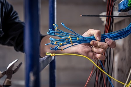
What Are Instrumentation Cables? Types, Uses & Selection Guide
Reading Time: 13 minutes
Instrumentation cable types carry low-level analogue and digital signals between field instruments, control systems and monitoring equipment. They commonly connect transmitters, sensors, PLCs, DCS systems, remote I/O and other process-control devices.
However, instrumentation cable is not one universal construction. Engineers can choose pairs, triads or other multi-element arrangements. In addition, the cable can use an overall screen, individual screens or both. Mechanical protection, insulation, sheath material and fire performance create further design choices.
For example, a conventional 4–20 mA transmitter circuit may use one twisted pair. By contrast, a three-wire RTD circuit can require a triad. Meanwhile, a high-EMI process plant may require individually screened pairs together with an overall screen.
Therefore, selecting instrumentation cable requires more than requesting a familiar RE-2X product code. Engineers should define the circuit, conductor size, pair or triad arrangement, screening, capacitance, voltage, mechanical protection, sheath and installation environment.
ETK Kablo manufactures a broad industrial measurement and process-control cable range for oil and gas, petrochemical, power, mining, manufacturing and infrastructure projects.
Quick answer: The main instrumentation cable types differ by pair or triad arrangement, overall or individual screening, insulation material, armour and outer sheath. Begin with the field-instrument circuit. Then define screening, conductor size, mechanical protection and fire requirements according to the actual installation.
Instrumentation Cable Types at a Glance
| Classification | Main Options | What It Defines |
|---|---|---|
| Circuit arrangement | Pair, triad, multi-pair, multi-triad | How conductors are grouped for instrument circuits |
| Screening | Overall, individual, individual + overall | EMI protection and circuit-to-circuit separation |
| Individual-screen terminology | PiMF, TiMF | Screen around each pair or triad |
| Insulation | XLPE, PE, PVC or project-specific material | Electrical and thermal characteristics |
| Outer sheath | PVC, halogen-free or project-specific | Environmental and fire-related material performance |
| Mechanical protection | Unarmored, SWA, SWB or other protection | Resistance to mechanical risks |
| Fire performance | Flame retardant, LSZH/HFFR, fire-resistant constructions | Different fire-related requirements |
| Installation | Indoor, outdoor, tray, duct, underground, exposed route | Physical environment |
As a result, two cables described simply as “instrumentation cable” can have very different electrical and mechanical constructions.
What Is an Instrumentation Cable?
An instrumentation cable connects measuring or control devices with the systems that receive and process their signals.
Typical field variables include:
- Pressure
- Temperature
- Flow
- Level
- Position
- Speed
- Process status
The cable can carry analogue or digital signals depending on the instrument and control system.
For example, many process transmitters use 4–20 mA current loops. Other systems can use low-level voltage, contact or digital communication circuits.
However, the cable itself does not define the signal protocol. The field device, I/O architecture and control system determine the electrical function.
How Is an Instrumentation Cable Constructed?
A typical construction begins with copper conductors and insulation.
Manufacturers then group the insulated conductors into pairs, triads or another required arrangement.
Depending on the design, the cable can also include:
- Class 2 stranded copper conductors
- XLPE, PE or PVC insulation
- Twisted pairs or triads
- Polyester wrapping
- Al/PET foil screens
- Tinned-copper drain or earth wires
- Individual pair or triad screens
- An overall screen
- An inner sheath
- SWA or SWB mechanical protection
- PVC or halogen-free outer sheath
Therefore, the finished design can combine electrical screening and mechanical protection independently.
Instrumentation Cable Types by Circuit Arrangement
The first major decision concerns conductor grouping.
The field circuit should normally determine whether the cable uses pairs or triads.
Pair Instrumentation Cable
A pair contains two insulated conductors twisted together as one functional element.
This architecture suits many two-conductor instrument circuits.
For example, a conventional two-wire 4–20 mA transmitter commonly uses one twisted pair.
In addition, a multi-pair cable can carry several separate instrument loops in one overall construction.
Triad Instrumentation Cable
A triad contains three insulated conductors grouped and twisted together.
Therefore, it suits circuits that require three related conductors to remain together.
Three-wire RTD circuits provide a common example.
However, triads are not automatically more precise or more resistant to EMI. Screening and circuit design remain separate engineering decisions.
For a deeper comparison, see our pair vs triad instrumentation guide.
Pair vs Triad: Start With the Instrument
The instrument wiring diagram should usually decide the cable-element arrangement.
Before selecting the cable, engineers should check:
- Number of conductors required by the device
- Whether those conductors form one functional circuit
- Signal type
- Power and signal arrangement
- Reference or return conductor requirements
- Screening requirements
For this reason, procurement teams should not select triads merely because they appear more advanced.
The cable architecture should follow the instrument circuit.
Instrumentation Cable Types by Screening
Screening protects sensitive signal circuits from unwanted electromagnetic coupling.
However, not every screen performs the same function.
The three main architectures are:
- Overall screen
- Individual pair or triad screens
- Individual screens plus an overall screen
Overall Screen
An overall screen surrounds the complete assembled cable core.
It mainly helps protect all internal circuits from external electromagnetic interference.
Common materials include Al/PET foil, copper braid or another suitable metallic system.
In addition, foil screens often use a drain or earth wire to support termination.
Individual Screen
An individual screen surrounds one pair or one triad before manufacturers assemble the complete cable.
This structure creates additional separation between neighbouring instrument circuits.
Therefore, individual screening can become valuable when several sensitive signals share one cable.
Individual Plus Overall Screen
More demanding designs can combine both architectures.
Each pair or triad receives its own screen. Then the complete cable core receives an additional overall screen.
As a result, the design addresses both internal circuit separation and external EMI.
Our individual vs overall screening guide explains this distinction in detail.
What Do PiMF and TiMF Mean?
PiMF means Pair in Metal Foil.
TiMF means Triad in Metal Foil.
In a PiMF construction, each pair receives its own foil screen. In a TiMF construction, each triad receives an individual foil screen.
Some products also add an overall screen around the complete group.
Therefore, the terms PiMF and TiMF describe the screening of individual cable elements. They do not automatically define armour, sheath material or fire performance.
For more detail, see our PiMF vs TiMF comparison.
Why Does Screening Matter?
Industrial plants contain many electrical-noise sources.
Typical examples include:
- Variable-frequency drives
- Large motors
- Power converters
- Transformers
- Switchgear
- High-current cables
- Electrical distribution systems
These sources can couple unwanted electrical noise into low-level instrument circuits.
Therefore, engineers should consider cable routing, pair twisting, screen architecture and grounding together.
However, shielding cannot compensate for every poor installation practice. Cable separation and correct termination remain important.
Does Every Instrumentation Cable Need a Screen?
No.
BS EN 50288-7 covers multi-element instrumentation and control cables that may be screened or unscreened. It can also cover optional armour and environmental protection layers.
However, many industrial instrumentation projects specify screening because the signals can operate in electrically noisy environments.
Therefore, do not assume that “instrumentation cable” automatically means one universal screened design.
The project should define the required screen architecture explicitly.
Instrumentation Cable Types by Mechanical Protection
Electromagnetic screening and mechanical armour perform different jobs.
A foil or braid screen primarily addresses electrical interference.
By contrast, armour protects the cable from physical stress.
Unarmored Instrumentation Cable
An unarmored design can work well on protected trays, inside buildings or inside another mechanically protective pathway.
As a result, the project avoids unnecessary weight and diameter.
ETK Kablo’s RE-2X(St)Y construction provides an example of an overall-screened, unarmored PVC-sheathed design.
SWA Instrumentation Cable
SWA uses galvanized steel wires around the inner cable structure.
The armour can add substantial mechanical protection and tensile reinforcement in suitable designs.
However, outdoor or underground installation does not automatically require SWA.
A protected duct or tray may create a very different mechanical environment from direct burial.
For the mechanical selection logic, see our SWA instrumentation cable guide.
Steel Wire Braid
Steel wire braid provides another form of metallic mechanical protection.
Its behaviour differs from conventional SWA because the wire geometry and cable flexibility differ.
Therefore, buyers should compare actual crush, tensile, impact and installation requirements instead of using “armored” as one generic specification.
Screening vs Armour
| Feature | Screen | Armour |
|---|---|---|
| Main purpose | Electromagnetic protection | Mechanical protection |
| Typical materials | Al/PET foil, copper braid | Galvanized steel wire or braid |
| Reduces external EMI | Yes, according to design | Not its primary purpose |
| Protects against crushing | Limited | Yes, according to design |
| Protects against impact | Limited | Yes, according to design |
| Can coexist in one cable | Yes | Yes |
Consequently, a technically complete RFQ should define the screen and armour separately.
XLPE, PE and PVC Insulation
Instrumentation cable families can use different insulation materials.
ETK’s RE-2X constructions commonly use XLPE insulation.
Other instrumentation families can use PE or PVC according to the specific cable design.
Each material changes electrical and thermal characteristics.
Therefore, engineers should not compare product codes only by sheath or armour.
The insulation system also forms part of the cable’s electrical performance.
Instrumentation Cable Types by Sheath Material
The outer sheath protects the cable against its installation environment.
PVC and halogen-free compounds represent two common choices in ETK instrumentation families.
PVC-Sheathed Instrumentation Cable
PVC provides a practical combination of durability, processability and cost efficiency.
For this reason, many industrial instrumentation cables use PVC outer jackets.
However, a PVC sheath does not define the complete fire performance of the cable.
Halogen-Free Instrumentation Cable
Halogen-free compounds reduce halogen-related corrosive gases during combustion.
They can also form part of low-smoke cable constructions.
For example, ETK’s RE-2X(St)H family uses a halogen-free outer sheath and lists product-specific smoke, corrosive-gas and flame tests.
However, LSZH or HFFR does not automatically mean fire resistant.
Fire resistance requires separate construction and test evidence.
Flame Retardant, LSZH and Fire Resistant Are Different
These terms frequently create confusion in instrumentation specifications.
Flame retardant describes the cable’s behaviour regarding flame propagation under a defined test.
LSZH / HFFR describes material characteristics related to smoke and halogen content.
Fire resistant addresses functionality or circuit integrity during specified fire exposure.
Therefore, one property does not automatically prove the others.
If a project requires signal continuity during fire exposure, engineers should specify a dedicated fire-resistant instrumentation construction and the exact test requirement.
What Is RE-2X(St)H?
RE-2X(St)H is a common halogen-free instrumentation-cable family.
ETK’s standard construction includes:
- Class 2 stranded copper conductor
- XLPE insulation
- Layered cable construction
- Al/PET overall screen
- Tinned-copper earth wire
- Halogen-free outer sheath
Therefore, the product combines XLPE insulation, overall EMI screening and a halogen-free jacket without steel-wire armour.
What Is RE-2X(St)Y?
RE-2X(St)Y follows a similar overall-screened instrumentation concept but uses a PVC outer sheath.
As a result, the major difference from RE-2X(St)H lies in the outer material system.
However, project engineers should still compare the complete datasheets rather than changing only one letter in the designation.
What Is RE-2X(St)YSWAY?
RE-2X(St)YSWAY adds galvanized steel wire armour to a PVC-based instrumentation construction.
Therefore, the cable combines overall EMI screening with additional mechanical protection.
It can suit routes that face mechanical risk when the complete project specification supports the construction.
However, SWA should follow the route requirements rather than become an automatic choice for every outdoor installation.
What Is RE-2X(St)HSWAH?
RE-2X(St)HSWAH combines halogen-free inner and outer sheath materials with steel wire armour.
Consequently, the design addresses mechanical protection and halogen-free material requirements together.
Different versions can use overall screening or individual PiMF/TiMF screening according to the circuit requirement.
For a direct family comparison, see our RE-2X(St) cable comparison.
Overall Screen vs PiMF/TiMF RE-2X Cables
An overall-screened RE-2X construction protects the complete cable core with one common screen.
By contrast, a PiMF/TiMF version screens each pair or triad separately.
Selected ETK constructions then add another overall screen outside those individually screened elements.
For example, the RE-2X(St)HSWAH PiMF/TiMF construction uses individual Al/PET screens, individual earth wires and an additional overall screen before the SWA layer.
Therefore, the screening requirement should come from the instrument loops and project EMC philosophy.
Instrumentation Cable Electrical Parameters
Instrumentation cable selection requires more than conductor size and screen type.
Important electrical parameters can include:
- Conductor resistance
- Insulation resistance
- Mutual capacitance
- Capacitance unbalance
- Operating voltage
- Test voltage
- Screen characteristics
These parameters influence how the cable behaves in the intended signal circuit.
For this reason, procurement teams should compare actual numerical values from the datasheet.
Why Does Capacitance Matter?
Every cable has electrical capacitance.
As cable length increases, the total capacitance seen by the circuit also increases.
This can matter in sensitive analogue, digital or intrinsically safe circuits.
Therefore, long instrument loops may require project-specific capacitance limits.
Engineers should use the control-system and hazardous-area design requirements rather than one universal capacitance rule.
Instrumentation Cable and Intrinsically Safe Circuits
Oil and gas projects often contain intrinsically safe instrument circuits.
However, intrinsic safety is a complete system concept.
The cable alone does not make a circuit intrinsically safe.
Instead, engineers must evaluate cable capacitance, inductance, loop length, connected apparatus and the relevant entity or system parameters.
Therefore, cable selection should follow the hazardous-area engineering documentation.
Can Standard Instrumentation Cable Be Used for Thermocouples?
Do not assume so.
Direct thermocouple extension and compensating circuits can require conductors made from specific thermocouple or compensating alloys.
A conventional copper instrumentation cable does not automatically reproduce those electrical characteristics.
Therefore, engineers should follow the temperature-sensor and thermocouple specification before choosing the cable.
Instrumentation Cable Types for Oil & Gas
Oil and gas facilities create demanding electromagnetic, mechanical and environmental conditions.
Typical projects include:
- Refineries
- Petrochemical plants
- Gas-processing facilities
- LNG terminals
- Tank farms
- Offshore facilities
These projects can require pair or triad constructions, individual screening, SWA, halogen-free sheaths and strict electrical parameters.
However, no single “oil and gas cable” suits every loop.
For detailed procurement logic, see our oil and gas instrumentation specification guide.
Instrumentation Cables in Power Plants
Power-generation facilities contain both sensitive instrumentation and high-power electrical equipment.
As a result, EMI management can become important.
Project teams may also require flame, smoke, halogen or mechanical performance according to the installation area.
Therefore, screening and fire requirements should follow the actual plant specification.
Instrumentation Cables in Mining
Mining installations can create severe mechanical and environmental conditions.
Routes may face vibration, impact, crushing, moisture or chemical exposure.
Consequently, some mining circuits can benefit from armored instrumentation constructions.
However, engineers should still define the measurable mechanical requirement rather than assume that the heaviest armour is always correct.
Instrumentation Cables in Water and Process Plants
Water-treatment and manufacturing facilities use instruments for pressure, flow, level and process monitoring.
Many of these circuits operate over significant cable lengths.
Therefore, conductor resistance, screening and installation routing can influence the final selection.
In addition, wet or chemically exposed areas may require a project-specific sheath or protection strategy.
Instrumentation Cable vs Control Cable
Instrumentation and control cables can appear in the same plant, but they often serve different circuit priorities.
Instrumentation cables commonly carry measurement and process signals.
Control cables often handle commands, switching functions, relays, contactors and actuator circuits.
In addition, instrumentation cables frequently use pair or triad structures and more detailed screening architectures.
Therefore, engineers should classify the actual circuit rather than use the two terms interchangeably.
Instrumentation Cable vs Signal Cable
Signal cable is a broader term.
It can describe many low-level analogue or digital connections outside formal process instrumentation.
Instrumentation cable usually places greater emphasis on process loops, pair or triad organization, electrical parameters and screening.
As a result, a general signal cable should not automatically replace an instrumentation cable specified for an industrial process project.
Instrumentation Cable vs Power Cable
Instrumentation cables should not serve as general power-distribution cables.
BS EN 50288-7 specifically covers analogue, digital and control circuits rather than direct connection to mains or other low-impedance power sources.
Therefore, power distribution requires the appropriate power-cable family.
This distinction remains important even when an instrumentation product carries a voltage marking that appears similar to another cable family.
EN 50288-7 Instrumentation Cables
EN 50288-7 provides an important European framework for multi-element metallic instrumentation and control cables.
The standard covers cables for analogue and digital signal transmission in industrial and commercial processes.
It also addresses electrical, mechanical, transmission and environmental characteristics.
In addition, the framework allows screened or unscreened constructions and optional armour or environmental-protection layers.
BSI currently lists BS EN 50288-7 as the current instrumentation and control cable standard in its catalogue.
Therefore, specifying only “EN 50288-7 cable” still does not define the complete construction. The RFQ must also state pair or triad arrangement, screening, materials and armour.
How to Choose Instrumentation Cable Types
1. Identify the Instrument Circuit
First, review the field-device wiring diagram and I/O schedule.
2. Select Pair or Triad
Match the cable element to the number of related conductors in the circuit.
3. Choose the Conductor Size
Consider resistance, loop length, voltage drop and terminal requirements.
4. Define the Screen Architecture
Specify overall screen, individual PiMF/TiMF screens or both.
5. Review Electrical Parameters
Check capacitance, resistance, voltage and other project limits.
6. Define Mechanical Protection
Use route-specific crush, impact, tensile and rodent risks to decide whether armour is necessary.
7. Choose the Material System
Select insulation and sheath materials according to electrical, environmental and fire requirements.
8. Define Fire Performance
Separate flame retardancy, LSZH requirements and fire-resistant circuit integrity.
9. Check the Installation Environment
Specify indoor, outdoor, tray, duct, underground or exposed installation.
10. Verify Documentation
Finally, confirm datasheets, standards, test reports and project-specific inspection requirements.
Instrumentation Cable Selection Matrix
| Requirement | Good Starting Direction |
|---|---|
| Two-wire instrument loop | Twisted pair |
| Three-wire instrument circuit | Triad |
| General external EMI protection | Overall-screened construction |
| Multiple sensitive circuits | Individual PiMF/TiMF screening |
| Internal isolation plus external EMI | Individual + overall screens |
| Protected installation route | Unarmored construction may be sufficient |
| High mechanical risk | Evaluate SWA, SWB or other protection |
| Halogen-free requirement | H-family / appropriate HFFR construction |
| PVC material acceptable | Y-family / suitable PVC construction |
| Fire circuit integrity required | Dedicated fire-resistant instrumentation design |
This table provides a starting point. The instrument schedule and project specification should make the final decision.
Common Instrumentation Cable Selection Mistakes
Assuming Every Instrumentation Cable Is Individually Screened
Overall-screened and individually screened constructions solve different requirements.
Choosing PiMF or TiMF Without Reviewing the Circuit
Pair or triad selection should follow the field instrument wiring.
Assuming More Screens Are Always Better
Additional screening increases diameter, material and termination work. Use it when the circuit requires it.
Confusing Screen With Armour
The screen addresses EMI. Armour addresses mechanical risk.
Using SWA for Every Outdoor Route
Outdoor exposure does not automatically create the same mechanical requirement as direct burial.
Assuming LSZH Means Fire Resistant
Halogen-free material and circuit integrity are separate properties.
Ignoring Cable Capacitance
Long and sensitive loops can require defined electrical limits.
Using Ordinary Copper Cable for Thermocouple Extension
Thermocouple circuits can require dedicated conductor alloys.
Calling a Cable Intrinsically Safe
Intrinsic safety depends on the complete loop and hazardous-area design.
Specifying Only a Product Code
One product-family code can still have several screening, armour and material variants.
What Should an Instrumentation Cable RFQ Include?
A professional RFQ should describe the circuit and cable construction clearly.
Include at least:
- Pair, triad or other circuit arrangement
- Number of pairs or triads
- Conductor cross-section
- Conductor class
- Overall screen requirement
- PiMF or TiMF requirement
- Individual and overall screen combination where required
- Screen material
- Drain or earth wire requirement
- Insulation material
- Outer-sheath material
- Operating voltage
- Conductor-resistance limit
- Capacitance requirement
- Armour or mechanical protection
- Indoor, outdoor, tray, duct or underground installation
- Fire-performance requirements
- Hazardous-area electrical parameters where applicable
- Applicable standard
- Drum length
- Cable marking
- Inspection and test documentation
As a result, manufacturers can quote technically equivalent constructions. Moreover, procurement teams can compare commercial offers on the same basis.
ETK Kablo Instrumentation Cable Solutions
ETK Kablo manufactures instrumentation cables for process control, industrial automation, oil and gas, petrochemical, power, mining and infrastructure projects.
The portfolio includes:
- Overall-screened RE-2X constructions
- PiMF individually screened pairs
- TiMF individually screened triads
- Individual plus overall screening
- PVC outer-sheath variants
- Halogen-free constructions
- Unarmored designs
- SWA armored designs
- Steel wire braided constructions
- Fire-resistant project-specific designs
Therefore, engineers can define the signal architecture, electrical parameters, screening and mechanical protection independently.
This approach allows the cable construction to follow the actual instrument loop rather than forcing every process application into one standard product.
Frequently Asked Questions
What are the main instrumentation cable types?
Instrumentation cable types include pair and triad constructions, overall-screened cables, individually screened PiMF/TiMF designs, armored and unarmored versions, and PVC or halogen-free material systems.
What is an instrumentation cable used for?
It carries analogue or digital signals between field instruments and control, monitoring or data-acquisition systems.
What is the difference between pair and triad cable?
A pair contains two related conductors. A triad contains three. The field-instrument wiring should determine which arrangement the project uses.
What does St mean in instrumentation cable?
In common RE cable nomenclature, St refers to an overall screened construction, typically using metallic foil with an earth or drain wire.
What does PiMF mean?
PiMF means Pair in Metal Foil. Each pair receives an individual metallic foil screen.
What does TiMF mean?
TiMF means Triad in Metal Foil. Each triad receives its own foil screen.
Is individual screening better than overall screening?
Not universally. Individual screening improves separation between circuits, while an overall screen mainly protects the grouped cable core from external EMI.
What is RE-2X(St)H?
It is an XLPE-insulated, overall-screened instrumentation-cable family with a halogen-free outer sheath.
What is RE-2X(St)YSWAY?
It combines XLPE-insulated instrumentation elements, overall screening, PVC sheath components and galvanized steel wire armour.
Does instrumentation cable need armour?
Only when the route requires additional mechanical protection. A protected tray or duct can have different needs from a direct-burial or exposed route.
Can instrumentation cable be used outdoors?
Yes, when the exact construction suits UV, moisture, temperature and mechanical conditions of the route.
Is LSZH instrumentation cable fire resistant?
Not automatically. LSZH material performance, flame retardancy and fire-resistant circuit integrity are separate requirements.
Can instrumentation cable carry 4–20 mA signals?
Yes. Twisted-pair instrumentation cables commonly carry 4–20 mA process-control loops when the electrical parameters suit the circuit.
Should RTD circuits use pairs or triads?
Three-wire RTD circuits commonly suit triad constructions because three related conductors remain grouped together.
Can standard instrumentation cable be used for thermocouples?
Do not assume so. Direct thermocouple extension circuits can require dedicated thermocouple or compensating conductor materials.
What standard applies to instrumentation cables?
EN 50288-7 provides an important European specification for multi-element metallic instrumentation and control cables. Projects can also impose additional customer or application-specific standards.
Conclusion: How Should You Choose Instrumentation Cable Types?
Instrumentation cable types should be selected from the instrument circuit outward.
First, determine whether the field device needs a pair, triad or another conductor arrangement. Then choose conductor size and review the required electrical parameters.
Next, define screening. An overall screen can protect the complete cable core from external interference. By contrast, PiMF or TiMF adds separation between individual instrument circuits.
Afterwards, evaluate mechanical protection. SWA, SWB and other reinforcement systems should follow the actual route rather than a general assumption that every industrial or outdoor cable needs armour.
Material and fire requirements form another separate decision. PVC, halogen-free, flame-retardant and fire-resistant constructions describe different performance areas.
Finally, verify the exact datasheet, project specification and applicable standard. This approach creates a cable that matches the electrical, electromagnetic, mechanical and environmental requirements without unnecessary overengineering.
Benzer yazılar
Ethernet Cable Testing: NEXT, Return Loss, Insertion Loss and ACR Explained
Ethernet cable testing verifies whether a twisted-pair copper cabling system can transmit data within the electrical performance limits...

Fiber Optic Cable Attenuation: 850, 1310, 1550 and 1625 nm Explained
Fiber optic cable attenuation describes the reduction in optical power as light travels through an optical fiber. It is normally expres...
A-02YSF(L)2Y vs A-2Y(L)2Y Outdoor Telephone Cable
A-02YSF(L)2Y vs A-2Y(L)2Y is an important comparison when selecting copper outdoor telephone cable for telecommunications networks, und...
RS-485 Cable vs Instrumentation Cable: Can Instrumentation Cable Be Used for Modbus RTU?
A Modbus RTU cable must do more than carry a low-voltage digital signal from one device to another. Modbus RTU commonly uses an RS-485 ...

Ethernet Cable for PoE: Conductor Size, Heat and Bundle Performance
A PoE Ethernet cable carries data and electrical power over the same balanced twisted-pair cabling system. This capability simplifies t...
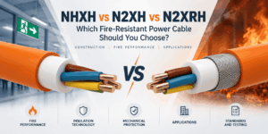
NHXH vs N2XH vs N2XRH: Which Fire-Resistant Power Cable Should You Choose?
NHXH vs N2XH vs N2XRH is an important comparison when specifying 0.6/1 kV power cables for emergency and life-safety systems. Although ...
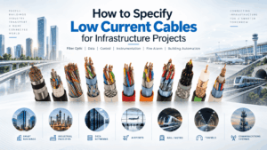
How to Specify Low Current Cables for Infrastructure Projects
A professional low current cable specification should define much more than a cable name, conductor count or sheath colour. Infrastruct...
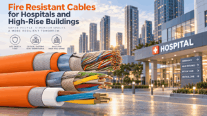
Fire Resistant Cables for Hospitals and High-Rise Buildings
Fire resistant cable for hospitals and high-rise buildings supports electrical, communication and control systems that may need to rema...
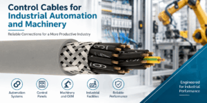
Industrial Control Cable Selection for Automation and Machinery
Industrial control cable selection should begin with the function of the circuit and the mechanical conditions of the machine rather th...
FE180 Fiber Optic Cable: Fire Integrity, Applications and Selection
An FE180 fiber optic cable is designed for optical communication routes where continued transmission during fire can form part of the p...
Screened vs Unscreened Control Cable: What Is the Difference?
Control cable shielding is one of the most important design decisions when selecting cable for industrial automation, machinery, buildi...

BMS Cable Selection: Building Automation Cables for HVAC and Smart Buildings
BMS cable selection should begin with the communication protocol and physical layer rather than with a generic request for “building au...


