





 President’s Message
Blog
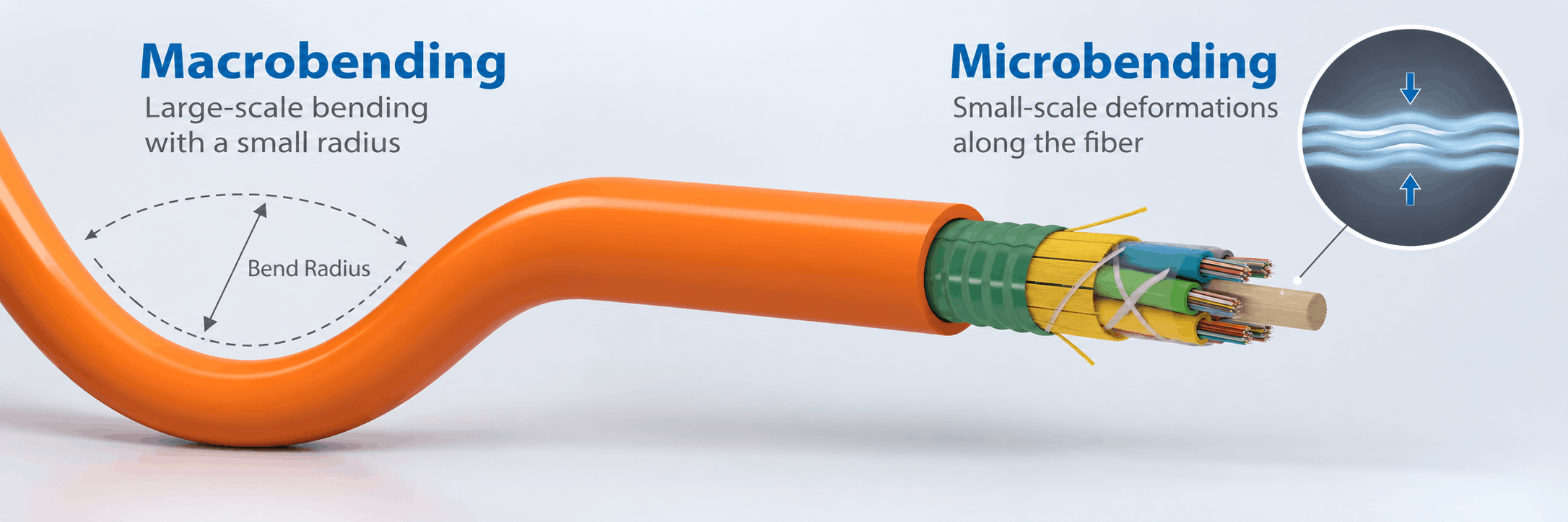
Fiber Optic Cable Bend Radius: Macrobending vs Microbending Explained
Reading Time: 20 minutes
Fiber optic bend radius is one of the most important installation limits in an optical cable system. A fiber cable can meet its attenuation, tensile, crush and impact requirements in the laboratory yet still experience unexpected optical loss if installers bend it too tightly during routing, pulling, termination or storage.
Excessive bending affects optical transmission because light must remain confined within the fiber core. When the fiber curvature becomes too severe, part of the guided optical energy can escape or the fiber can experience localized mechanical distortion.
Two different mechanisms are particularly important: macrobending and microbending.
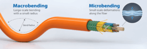
Macrobending occurs when the fiber follows a visibly curved path with an excessively small radius. Microbending, by contrast, consists of very small localized distortions along the fiber axis, often caused by pressure, manufacturing stress, cable deformation or temperature-related movement.
Although both mechanisms can increase attenuation, their physical causes are different. Therefore, engineers should distinguish between cable bend radius, fiber-level bending sensitivity and small-scale microbending pressure when specifying or troubleshooting an optical network.
Quick answer: minimum fiber optic bend radius defines how tightly a complete cable may be curved without creating unacceptable mechanical stress or optical loss. Macrobending results from larger visible curves, loops or tight routing. Microbending results from microscopic local deformations caused by pressure or internal cable stresses. G.657 bend-insensitive single-mode fibers reduce macrobending loss, but they do not eliminate the need to follow the finished cable manufacturer’s minimum bending radius.
Fiber Optic Bend Radius at a Glance
| Parameter | Meaning | Main Risk |
|---|---|---|
| Minimum bend radius | Smallest permitted cable curvature | Optical loss and mechanical damage |
| Macrobending | Large-scale visible fiber curvature | Light leakage and increased attenuation |
| Microbending | Microscopic local fiber distortion | Mode coupling and attenuation increase |
| Dynamic / installation bend | Bending while cable is under installation stress | Combined tensile and bending strain |
| Fixed bend | Permanent bend after installation | Long-term attenuation and fiber stress |
| G.657 fiber | Bend-insensitive single-mode fiber | Reduces macrobending sensitivity |
| IEC E11 bend test | Standardized cable bending qualification | Attenuation change and physical damage |
Consequently, bend radius should not be treated merely as an installation convenience. It is both an optical and mechanical design parameter.
What Is Fiber Optic Bend Radius?
Fiber optic bend radius describes the permitted curvature of a fiber optic cable or optical fiber.
The value is normally specified as either:
- A fixed radius in millimetres
- A multiple of the cable outside diameter
For example, a manufacturer can specify:
- 15 × cable diameter for fixed installation
- 20 × cable diameter during installation or another operating condition
If a cable has an outside diameter of 10 mm, a requirement of 20 × D corresponds to a 200 mm minimum bend radius.
However, the exact multiplier varies by cable construction. Therefore, engineers should use the value published for the specific product rather than apply one universal rule to every fiber optic cable.
Why Fiber Optic Bend Radius Matters
Optical fibers guide light through the relationship between the core and surrounding cladding.
Under normal conditions, most of the optical energy remains confined to the intended propagation region.
However, severe curvature changes the geometry through which the guided light travels.
As a result, some optical energy can leave the guided mode and become lost.
Excessive bending can also produce mechanical strain in the glass or deformation in the surrounding tube and cable components.
Therefore, bending can affect both transmission performance and long-term cable reliability.
What Is Macrobending in Fiber Optic Cable?
Macrobending refers to relatively large-scale curvature of the optical fiber compared with the diameter of the fiber itself.
Typical examples include:
- A cable routed around a corner too tightly
- A small loop behind a patch panel
- Fiber wrapped around a narrow mandrel
- A tight coil inside a closure
- A cable forced through an undersized bend
The bend can often be seen with the naked eye.
As the bend radius becomes smaller, macrobending loss generally increases.
Consequently, a cable that performs normally while straight can show measurable additional attenuation when routed through an excessively tight bend.
How Macrobending Causes Optical Loss
Light travelling through an optical fiber follows the geometry of the fiber.
When the fiber curves gradually, the guided optical modes remain largely confined.
However, as the radius becomes smaller, the electromagnetic field associated with the guided light can no longer remain completely confined within the intended region.
Some energy therefore radiates away from the fiber.
This creates additional attenuation.
Importantly, the effect can occur without the glass physically breaking.
Therefore, a tight bend can create a network fault even though the cable still appears mechanically intact.
What Is Microbending in Fiber Optic Cable?
Microbending is fundamentally different from macrobending.
Instead of one large visible curve, microbending consists of very small localized axial distortions along the optical fiber.
These distortions can be only a few micrometres in scale and may not be visible during ordinary inspection.
Potential causes include:
- Localized pressure
- Crushing
- Tight cable ties
- Improper buffering
- Manufacturing stresses
- Tube deformation
- Temperature-related contraction
- Uneven pressure from cable components
Consequently, microbending can increase optical attenuation even when the overall cable follows a generous bend radius.
Macrobending vs Microbending
| Characteristic | Macrobending | Microbending |
|---|---|---|
| Scale | Large visible curvature | Microscopic localized distortion |
| Typical cause | Tight routing or coiling | Pressure or internal stress |
| Visible to installer | Often | Usually not |
| Related to cable bend radius | Directly | Indirectly |
| Can increase attenuation | Yes | Yes |
| Reduced by G.657 fiber | Strongly | Depends on fiber and cable design |
| Can result from crushing | Not normally the primary mechanism | Yes |
Therefore, diagnosing bend-related attenuation requires understanding whether the problem comes from overall routing geometry or localized mechanical pressure.
Fiber Optic Bend Radius vs Microbending
A common misconception is that following the specified fiber optic bend radius completely eliminates bending-related attenuation.
That is not necessarily true.
A cable can follow a large and acceptable overall curve while still experiencing localized pressure inside the cable.
For example, an overtightened clamp can compress one small section of an otherwise correctly routed cable.
The visible bend radius can remain acceptable while microbending develops internally.
Therefore, installers must control both curvature and localized mechanical pressure.
What Causes Macrobending?
Macrobending commonly results from installation geometry.
Typical causes include:
- Tight 90-degree corners
- Small service loops
- Overfilled cable trays
- Improper cable storage
- Tight routing behind racks
- Undersized ducts or conduits
- Incorrect drum handling
- Sharp changes in pathway direction
In addition, installers can accidentally pull a loop until it becomes extremely small.
Therefore, bend-radius control should be considered during route design as well as during field installation.
What Causes Microbending?
Microbending can originate from forces applied directly to the optical fiber or indirectly through surrounding cable components.
Potential sources include:
- Excessive crush pressure
- Buffer contraction
- Uneven tube pressure
- Hard cable components pressing against fibers
- Excessive jacket shrinkage
- Temperature cycling
- Tight restraints
- Improper manufacturing tension
Because the distortion can be extremely small, microbending problems can be difficult to identify through visual inspection alone.
Instead, increased attenuation or OTDR events can provide the first indication of a problem.
Fiber Optic Bend Radius During Installation
Installation is often one of the most mechanically demanding periods in the life of a fiber optic cable.
The cable can simultaneously experience:
- Tensile load
- Bending
- Sidewall pressure
- Friction
- Torsion
For this reason, the permitted bend radius during installation is often larger than the radius permitted after the cable has been placed and unloaded.
Combining high pulling tension with a small bend radius can create significant fiber strain.
Therefore, installers should follow both maximum pulling tension and bend-radius limitations at the same time.
Fixed vs Dynamic Fiber Optic Bend Radius
Many cable datasheets distinguish between fixed and non-fixed or installation-related bending conditions.
A fixed cable remains relatively stationary after installation.
By contrast, a cable under installation load can experience additional tensile and mechanical stress.
As a result, manufacturers often specify a more conservative radius for the mechanically demanding condition.
For example, a product might permit a smaller radius after final installation while requiring a larger radius during pulling.
However, terminology varies between manufacturers.
Therefore, engineers should interpret the definitions used in the exact datasheet rather than assume that every manufacturer uses identical labels.
Understanding 10 × D, 15 × D and 20 × D
Fiber optic cable bend radius is frequently expressed as a multiple of cable diameter.
The letter D represents the cable outside diameter.
For a 12 mm cable:
| Requirement | Minimum Radius |
|---|---|
| 10 × D | 120 mm |
| 15 × D | 180 mm |
| 20 × D | 240 mm |
Consequently, high-fiber-count or heavily armored cables can require substantially more routing space because their outside diameters are larger.
Bend Radius vs Bend Diameter
Radius and diameter should not be confused.
A radius represents half of the corresponding circular diameter.
Therefore, a cable requiring a 200 mm bend radius needs approximately a 400 mm bend diameter for a complete circular path.
This distinction becomes especially important when designing:
- Cable trays
- Pulling wheels
- Handholes
- Joint chambers
- Racks
- Splice closures
Accordingly, drawings should state clearly whether a dimensional requirement refers to radius or diameter.
Why Cable Diameter Changes Bend Radius
Many optical cables use bend limits proportional to their outside diameter because the mechanical strain created by bending depends partly on cable geometry.
A larger cable places the outer portions of the cable structure farther from the neutral bending axis.
Consequently, the same physical radius can create more deformation in a larger construction.
This is one reason large armored or high-fiber-count cables often need significantly more bend space than small indoor cables.
Fiber Optic Bend Radius and Wavelength
Macrobending loss depends on wavelength.
For single-mode fiber, longer wavelengths are generally more sensitive to bending loss.
Therefore, bend-related problems can become more apparent at:
- 1550 nm
- 1625 nm
than at shorter single-mode wavelengths under otherwise comparable conditions.
This is one reason macrobending performance is often evaluated at the longer wavelengths used by the fiber system.
Why 1625 nm Can Reveal Bend Problems
At longer wavelengths, the optical mode extends farther into the cladding region.
Consequently, tight curvature can allow optical energy to escape more readily.
Therefore, a bend that produces relatively little loss at 1310 nm can create more noticeable attenuation at 1550 or 1625 nm.
This behavior can help technicians distinguish bend-related events during network troubleshooting.
Fiber Optic Bend Radius and G.652.D Fiber
ITU-T G.652.D is widely used for long-distance single-mode telecommunications networks.
It provides excellent attenuation, dispersion and compatibility characteristics for backbone and access networks.
However, conventional G.652.D fiber is generally more sensitive to very small bending radii than fiber specifically optimized for bend-insensitive performance.
Therefore, projects involving compact routing or tight fiber-management systems can benefit from G.657 fiber.
Fiber Optic Bend Radius and G.657 Fiber
ITU-T G.657 defines bend-loss-insensitive single-mode optical fibers.
These fibers are engineered to reduce macrobending loss at smaller radii.
Common categories include:
- G.657.A1
- G.657.A2
- G.657.B3
Category A fibers are designed to maintain compatibility with G.652.D network requirements while improving bend performance.
Category B fibers are optimized for especially demanding short-reach applications involving very small bend radii.
G.657.A1 vs G.657.A2 Bend Performance
G.657.A1 and G.657.A2 both provide improved macrobending performance compared with conventional single-mode fiber.
However, A2 provides greater tolerance to smaller bends.
| Fiber Type | ITU-T Minimum Design Radius | General Positioning |
|---|---|---|
| G.657.A1 | 10 mm | Bend-insensitive, G.652.D-compatible applications |
| G.657.A2 | 7.5 mm | Higher bend tolerance for compact installations |
| G.657.B3 | 5 mm | Very small-radius short-reach applications |
Importantly, these values relate to fiber-level design and macrobending performance under specified ITU-T conditions.
They are not permission to bend an entire fiber optic cable to 5, 7.5 or 10 mm.
The finished cable can require a much larger bend radius because of its jacket, tubes, strength members, armour and complete mechanical construction.
Fiber Radius vs Fiber Optic Cable Bend Radius
This distinction is critical.
A bare G.657.A2 optical fiber can be designed for very small-radius applications.
However, once that fiber is incorporated into a cable, the complete construction determines the permitted cable curvature.
A cable can contain:
- PBT loose tubes
- FRP central strength members
- Steel wire
- Aramid yarn
- Corrugated steel armour
- Multiple jackets
These components do not necessarily tolerate the same radius as the bare optical fiber.
Therefore, installers must always follow the finished cable bend radius rather than substitute the ITU-T fiber-level radius.
Does G.657 Eliminate Macrobending?
No.
G.657 significantly reduces macrobending loss at small radii, but bend-insensitive does not mean bend-proof.
Excessively tight curvature can still:
- Increase attenuation
- Stress the glass
- Damage cable components
- Reduce long-term reliability
Consequently, G.657 provides additional engineering margin but does not eliminate good cable-management practices.
Does G.657 Eliminate Microbending?
Not necessarily.
G.657 primarily addresses macrobending performance.
Microbending sensitivity also depends on:
- Fiber design
- Coating
- Buffering
- Cable construction
- Applied pressure
- Temperature
Therefore, even bend-insensitive fiber should be protected from crushing, overtightened ties and internal cable stress.
Fiber Optic Bend Radius and Loose-Tube Cable
Loose-tube cable provides mechanical isolation between the optical fibers and external cable movement.
The fibers have controlled excess length inside the tube.
As a result, moderate cable movement or longitudinal strain does not immediately translate into equivalent fiber strain.
However, the PBT tube itself has a mechanical bend limit.
If the cable bends excessively, the tube can deform and force the fibers into tighter curvature.
Therefore, loose-tube construction still requires strict bend-radius control.
Central Loose Tube vs Multi Loose Tube Bend Radius
Central and multi loose-tube designs distribute cable components differently.
A central loose-tube cable can provide a compact structure because fibers are housed within one central tube.
Multi loose-tube cables arrange multiple tubes around a central strength member.
Consequently, multi-tube cables with high fiber counts can become larger in diameter and may require correspondingly larger bending space.
Nevertheless, the exact manufacturer value should determine the minimum radius rather than the cable architecture alone.
Tight-Buffered Fiber Optic Bend Radius
Tight-buffered cables use buffer material directly around the coated optical fiber.
This construction is widely used indoors because it simplifies:
- Termination
- Connectorization
- Breakout
- Rack routing
Compact indoor pathways can make bend performance particularly important.
For this reason, G.657.A1 and G.657.A2 fibers are attractive in tight-buffered designs intended for data centers, telecommunications rooms and building distribution.
Fiber Optic Bend Radius in FTTH Networks
FTTH networks contain many locations where fibers must fit into compact spaces.
Examples include:
- Wall boxes
- Floor distribution boxes
- Optical termination outlets
- Building risers
- Subscriber premises
- Drop-cable pathways
Consequently, bend-insensitive G.657 fiber has become especially important in access-network deployments.
However, even FTTH drop cable should remain within the bend radius specified for the complete product.
Fiber Optic Bend Radius in Data Centers
Data-center fiber cabling can encounter dense cable management and limited space.
Potential problem areas include:
- Patch panels
- Vertical managers
- Horizontal managers
- Splice trays
- Overhead pathways
- High-density cassettes
Therefore, fiber-management hardware should maintain smooth cable paths and avoid sharp transitions.
In addition, bend-insensitive fibers can provide useful optical margin in high-density environments.
Fiber Optic Bend Radius in Duct Installations
Duct routes can create substantial combined tensile and bending stress.
Every change in direction increases pulling friction.
If a bend becomes too tight, sidewall pressure can rise while the cable remains under significant longitudinal load.
Therefore, engineers should consider:
- Pulling tension
- Bend radius
- Duct geometry
- Number of bends
- Pulling lubricant
- Cable diameter
Consequently, a duct cable should not simply be forced through a route because its physical diameter fits inside the conduit.
Fiber Optic Bend Radius in Direct Burial
Direct-burial cables can be relatively heavy and mechanically reinforced.
Armour, thick PE jackets and high fiber counts can increase cable stiffness.
During installation, bends can occur at:
- Trench transitions
- Handholes
- Building entries
- Joint closures
- Drum pay-off points
Therefore, installation planning should provide sufficient space to maintain the specified curvature throughout the route.
Fiber Optic Bend Radius in Aerial Cable
Aerial fiber cables can experience combined bending and tension during installation.
ADSS cable can also remain under substantial long-term tensile load after installation.
Consequently, cable routing around poles, suspension hardware and dead-end assemblies must respect the product’s mechanical limits.
Figure-8 designs with metallic messenger wires can have different bending behavior from all-dielectric designs.
Therefore, aerial installation hardware should match the specific cable construction.
Armored Fiber Optic Cable Bend Radius
Armour can significantly influence cable flexibility.
Common armour systems include:
- Corrugated steel tape
- Steel wire armour
- Steel braid
- Non-metallic reinforcement
Steel elements generally increase mechanical protection but can also increase stiffness.
As a result, heavily armored cables can require larger installation radii than lightweight dielectric designs.
Therefore, mechanical protection and routing flexibility should be considered together during cable selection.
Corrugated Steel Tape and Bend Radius
Corrugated steel tape is shaped to provide mechanical protection while preserving more flexibility than a completely rigid metallic tube.
Nevertheless, the metallic layer still affects bending behavior.
Excessive bending can permanently deform the armour or place abnormal pressure on the internal cable core.
Consequently, the finished cable manufacturer’s bend-radius value remains essential.
Steel Wire Armour and Bend Radius
Steel wire armour can provide substantial tensile and mechanical strength.
However, multiple steel wires arranged around the cable increase overall stiffness and diameter.
Therefore, an SWA-style fiber cable can require more routing space than a comparable non-metallic construction.
This trade-off should be considered early in tray, trench and equipment-room design.
Non-Metallic Fiber Cable and Bend Radius
FRP and aramid-reinforced constructions can provide strong tensile performance without heavy metallic armour.
These designs can offer useful flexibility and lower weight.
However, FRP rods themselves have mechanical bending limits.
Therefore, all-dielectric does not mean that the cable can be bent arbitrarily tightly.
Fiber Optic Bend Radius and Cable Kinking
Kinking is more severe than ordinary bending.
A kink can occur when a cable loop tightens suddenly during pulling.
This creates highly concentrated local curvature and can damage:
- Optical fibers
- Loose tubes
- Strength members
- Armour
- Outer jacket
Therefore, installers should never straighten a severely kinked cable and automatically assume that performance has returned to normal.
Optical testing can be necessary after significant mechanical damage.
Fiber Optic Bend Radius and Cable Ties
Cable ties can create a different problem.
An installer can maintain the correct visible cable radius but tighten a tie enough to create localized compression.
This pressure can contribute to microbending.
Therefore, fiber optic cables should be supported rather than tightly constricted.
Where appropriate, broad hook-and-loop fasteners can provide more distributed pressure than narrow plastic ties.
Fiber Optic Bend Radius and Cable Clamps
Clamps should support the cable without crushing or sharply deforming it.
Improperly sized clamps can create pressure points.
This becomes particularly important in aerial, industrial and vertical installations where clamps also carry mechanical load.
Therefore, accessories should be selected for the specific cable diameter and construction.
How Temperature Can Cause Microbending
Optical fibers, PBT tubes, strength members and outer jackets do not necessarily expand and contract at identical rates.
When temperature changes significantly, dimensional differences can create internal stress.
If cable design does not provide sufficient mechanical freedom, localized pressure can reach the fibers.
Consequently, microbending attenuation can appear during temperature cycling even when the cable remains straight.
This is one reason optical cable qualification includes environmental as well as mechanical testing.
Microbending and Loose-Tube Design
Loose-tube construction helps isolate fibers from some cable stresses.
However, microbending can still occur if:
- The tube deforms
- Excess fiber length is poorly controlled
- Internal fillers create pressure
- The tube contracts excessively
- The cable experiences severe crushing
Therefore, tube material and geometry are critical parts of optical cable engineering.
Microbending and Tight-Buffered Fiber
In tight-buffered cable, the fiber interacts more closely with the buffer material.
Consequently, buffer properties and manufacturing control strongly influence the mechanical relationship between polymer and glass.
A properly designed tight buffer protects the fiber while maintaining acceptable optical performance across the required temperature range.
Therefore, material selection and extrusion consistency are essential.
Fiber Optic Bend Radius and OTDR Testing
An OTDR can help identify bending-related attenuation events.
A strong bend can appear as a localized loss event along the fiber.
Comparing traces at different wavelengths can provide additional clues.
For example, a bend-related event can become more prominent at 1550 or 1625 nm than at 1310 nm.
Therefore, multi-wavelength testing can help distinguish a bend from some other network defects.
Macrobending vs Splice Loss on an OTDR
A poor splice and a macrobend can both appear as loss events.
However, their wavelength behavior can differ.
A conventional splice problem may show similar loss characteristics across several wavelengths, while a tight bend often becomes disproportionately worse at longer wavelengths.
Therefore, comparing 1310 nm and 1550 nm traces can provide useful diagnostic information.
Nevertheless, field interpretation should consider the complete link and test conditions rather than rely on one rule alone.
Can Bending Damage Fiber Without Immediate Failure?
Yes.
Fiber does not need to break completely for excessive bending to create a problem.
A cable can experience:
- Higher attenuation
- Residual mechanical stress
- Tube deformation
- Jacket distortion
- Reduced mechanical margin
Consequently, an installation can initially operate while still containing an unnecessarily stressed cable section.
Long-term reliability therefore requires respecting the manufacturer’s bend limits even when initial optical testing passes.
Can Macrobending Loss Recover?
In some cases, yes.
If a cable is bent temporarily without permanent mechanical damage, attenuation can return toward its original value when the bend is released.
However, recovery should not be assumed after severe deformation.
A tight bend can damage the tube, jacket, strength member or fiber itself.
Therefore, significant installation abuse should be investigated rather than simply straightened and ignored.
Can Microbending Loss Recover?
Microbending can also be reversible when the pressure causing the deformation is removed.
For example, loosening an excessively tight cable restraint can reduce the localized stress.
However, permanent deformation or material damage can leave residual attenuation.
Consequently, prevention remains preferable to corrective maintenance.
IEC Fiber Optic Bend Test
Fiber optic cable bending performance can be evaluated using standardized mechanical test procedures.
The current dedicated IEC cable bend method is IEC 60794-1-111, Method E11.
The procedure evaluates a cable while it is bent around a defined test mandrel.
Its primary objective is to measure attenuation change during the bending condition.
In addition, the test can evaluate whether bending creates physical damage.
Therefore, the IEC bend test links mechanical curvature directly with optical performance.
IEC E11 vs Minimum Fiber Optic Bend Radius
The E11 laboratory test should not be confused with the everyday installation limit published on a datasheet.
The test defines a controlled qualification procedure involving specified cable bending conditions.
By contrast, the minimum fiber optic bend radius tells installers how tightly the finished product may be routed in practice.
Therefore, the two values can be related without being interchangeable.
IEC Macrobending Test for Optical Fiber
The cable bend test and the bare-fiber macrobending test also serve different purposes.
IEC 60793-1-47 addresses measurement of macrobending loss in optical fibers.
The standard includes methods such as fiber winding around defined radii while optical attenuation is measured.
For single-mode fibers, measurements can be performed at wavelengths such as 1550 or 1625 nm.
Therefore, fiber-level macrobending qualification and complete-cable bend qualification should remain conceptually separate.
ITU-T G.657 Macrobending Requirements
ITU-T G.657 specifies maximum macrobending loss under defined combinations of radius, wavelength and number of turns.
The current recommendation differentiates G.657.A1, G.657.A2 and G.657.B3 according to their bend performance.
For example, A1 is intended for a minimum design radius of 10 mm, while A2 supports 7.5 mm and B3 is optimized for still smaller 5 mm-radius applications.
However, these values apply to optical fiber characteristics under defined conditions.
Consequently, they should not replace finished-cable installation specifications.
Fiber Optic Bend Radius Example from ETK Kablo
ETK Kablo outdoor fiber optic cable datasheets provide a useful example of how bend requirements appear in practice.
Several multi loose-tube outdoor constructions specify:
- Fixed minimum bending radius: 15 × cable diameter
- Another specified operating or installation-related condition: 20 × cable diameter
The same products are mechanically qualified using an E11 bend test with a radius based on approximately 20 × cable diameter.
Therefore, ETK’s product data clearly separates laboratory bend qualification from the practical minimum-radius information used by engineers and installers.
Example: 12 mm ETK Fiber Cable
Consider a fiber optic cable with an outside diameter of 12 mm.
Using a 15 × D fixed radius:
15 × 12 mm = 180 mm.
Using a 20 × D requirement:
20 × 12 mm = 240 mm.
Therefore, trays, conduit bends and joint chambers should provide enough space to maintain the relevant radius without forcing the cable against sharp surfaces.
Fiber Optic Bend Radius and Splice Closures
Splice closures contain significant lengths of exposed or lightly protected fiber.
Inside the closure, technicians must manage:
- Loose fibers
- Splice protectors
- Fiber trays
- Pigtails
- Tube entries
Consequently, bend management inside the closure can be even more critical than the bend radius of the incoming heavy cable.
G.657 fibers can provide useful margin, but technicians should still follow the tray manufacturer’s routing geometry.
Fiber Optic Bend Radius Inside Patch Panels
Patch panels create another common risk area.
High-density panels can encourage installers to force fiber jumpers into compact spaces.
Tight turns near adapters or cable-entry points can create macrobending.
Therefore, good panel design should provide:
- Guided routing paths
- Large-radius management rings
- Appropriate slack storage
- Strain relief
In addition, unnecessary excess cable should not be compressed behind the equipment.
Fiber Optic Bend Radius in Cable Trays
Cable trays should support smooth changes of direction.
A tray corner with insufficient radius can force every installed cable into an excessive bend.
This becomes particularly important for armored, large-diameter and high-fiber-count products.
Therefore, pathway design should use the largest required bend radius among the cables planned for the route.
Fiber Optic Bend Radius in Conduits
Conduit bends influence both curvature and pulling tension.
A small-radius elbow can create:
- Higher friction
- Greater sidewall pressure
- Higher pulling tension
- Tighter cable curvature
Consequently, conduit-route engineering should consider cable mechanics rather than only conduit fill.
Fiber Optic Bend Radius Around Pulling Sheaves
Pulling sheaves or rollers should maintain a sufficient radius while supporting the cable under tension.
An undersized roller can impose severe bending while the cable is simultaneously experiencing its highest installation load.
This combination is particularly undesirable.
Therefore, pulling hardware should be selected according to the cable diameter and manufacturer recommendations.
Common Fiber Optic Bend Radius Mistakes
Using One Bend Radius for Every Fiber Cable
Cable diameter, armour, fiber count and mechanical construction all influence the permissible curvature.
Confusing Fiber Radius with Cable Radius
A G.657.A2 fiber rating does not mean that the entire cable may be bent to 7.5 mm.
Confusing Radius with Diameter
A 200 mm radius corresponds to a 400 mm bend diameter.
Ignoring Installation Tension
A cable under high pulling force requires particularly careful bend control.
Assuming Bend-Insensitive Fiber Cannot Be Damaged
G.657 reduces optical bend loss but does not make the complete cable mechanically unrestricted.
Ignoring Microbending
Correct overall curvature does not protect the fiber from localized pressure.
Overtightening Cable Ties
Local compression can create microbending even when the route looks correct.
Using Undersized Rollers
Small pulling hardware can force the cable below its permitted installation radius.
Creating Tight Service Loops
Stored cable should preserve the minimum bend radius rather than form compact coils.
Overfilling Patch Panels
Dense fiber routing can create small-radius bends behind adapters and trays.
Straightening a Kink and Ignoring It
A severe kink can cause hidden mechanical or optical damage.
Testing Only at 1310 nm
Longer wavelengths can reveal bend-related loss more clearly in some single-mode networks.
Assuming Passing OTDR Means the Bend Is Acceptable
A route should still comply with mechanical limits even when current optical loss remains below the project threshold.
How to Specify Fiber Optic Bend Radius
Identify the Exact Cable Construction
Start with the cable diameter, fiber count, tube design, armour and strength-member architecture.
Use the Manufacturer Bend Radius
Do not substitute a generic 10 × D or 20 × D value unless the product specification supports it.
Separate Fixed and Installation Conditions
Define the applicable radius for the cable while being installed and after final placement.
Check Maximum Pulling Tension
Bending and longitudinal force should be assessed together during duct or conduit installation.
Select Appropriate Pathway Hardware
Trays, rollers, conduit bends and cable managers should accommodate the required radius.
Consider Fiber Type
G.657.A1 or A2 can provide useful macrobending margin where compact routing is expected.
Control Local Pressure
Use clamps and restraints that support the cable without creating microbending pressure points.
Review Operating Temperature
Temperature-related cable contraction can contribute to internal mechanical stress.
Plan Splice and Patch Management
Fiber-level routing inside closures and panels should maintain appropriate curvature.
Define Optical Acceptance Testing
Use the required attenuation and OTDR testing to verify that installation has not introduced excessive loss.
Fiber Optic Bend Radius RFQ Checklist
A professional fiber optic bend radius specification can include:
- Fiber type: G.652.D, G.657.A1, G.657.A2 or multimode
- Fiber count
- Central or multi loose-tube design
- Tight-buffered construction where applicable
- Cable outside diameter
- Minimum fixed bend radius
- Minimum installation bend radius
- Maximum installation tension
- Maximum operating tension
- Armour type
- Strength-member construction
- IEC E11 bend-test requirement
- Permitted attenuation change
- Test wavelength
- Repeated-bending requirement
- Operating temperature
- Installation temperature
- Duct, direct-burial, aerial or indoor installation
- Required mechanical test documentation
Consequently, the manufacturer can evaluate the cable’s complete mechanical and optical requirements rather than respond only to a request for a particular fiber count.
ETK Kablo Fiber Optic Bend Radius Solutions
ETK Kablo manufactures indoor, outdoor, duct, aerial, armored, non-metallic and fire-resistant fiber optic cables using a wide range of optical fiber types.
Available single-mode options include:
- G.652.D
- G.657.A1
- G.657.A2
Multimode configurations include OM1 through OM5 according to cable family and project requirement.
For compact indoor, FTTH and project-specific applications, G.657.A1 and G.657.A2 fibers provide improved macrobending performance.
Meanwhile, the finished cable construction determines the practical fiber optic bend radius used during installation and operation.
ETK outdoor and indoor fiber cable datasheets also specify mechanical test criteria such as tensile strength, crush resistance, impact, torsion, repeated bending and E11 bending performance.
Therefore, ETK can match fiber type and cable construction to both the optical bend requirements and the mechanical conditions of the project.
ETK Outdoor Fiber Optic Bend Example
ETK A-DQ(ZN)2Y outdoor multi loose-tube cable provides one representative example.
The published construction includes a defined minimum fixed bending radius and a separate larger radius for the other specified operating or installation condition.
The cable is also qualified through an E11 bending procedure using a radius based on the cable diameter and optical acceptance criteria.
Consequently, the product demonstrates how mechanical cable limits and optical attenuation limits are evaluated together.
ETK Indoor Bend-Insensitive Fiber Options
ETK indoor tight-buffered cable families are available with G.657.A1 and G.657.A2 single-mode fibers in addition to G.652.D.
These bend-insensitive options are particularly useful for:
- Data centers
- Telecommunications rooms
- Building risers
- FTTB
- MDU installations
- High-density optical distribution
However, the cable-level bend limit still depends on the complete tight-buffered construction.
Frequently Asked Questions About Fiber Optic Bend Radius
What is fiber optic bend radius?
It is the minimum permitted curvature of an optical fiber or complete fiber optic cable without unacceptable optical loss or mechanical stress.
What happens if fiber optic cable is bent too tightly?
Attenuation can increase because of macrobending, and excessive mechanical stress can also damage cable components or the fiber.
What is macrobending?
Macrobending is relatively large-scale fiber curvature with a radius small enough to cause additional optical loss.
What is microbending?
Microbending consists of microscopic localized fiber distortions usually created by pressure, material stress or manufacturing and environmental effects.
What is the difference between macrobending and microbending?
Macrobending results from overall fiber curvature, while microbending results from very small local distortions along the fiber.
Can microbending occur in a straight cable?
Yes. Localized pressure can produce microbending even when the overall cable route appears straight.
What does 20 × D mean?
It means the minimum bend radius is twenty times the cable outside diameter.
What is the difference between bend radius and bend diameter?
Bend diameter is twice the bend radius.
Does every fiber cable use 20 × D?
No. The required value depends on cable construction and manufacturer specifications.
Is installation bend radius different from fixed bend radius?
Often yes. Cable under pulling tension can require a larger radius than cable in its final unloaded position.
Which wavelength is most sensitive to macrobending?
For single-mode fiber, longer wavelengths such as 1550 and 1625 nm generally show greater sensitivity to tight bends.
Can a bend cause loss without breaking the fiber?
Yes. Optical attenuation can increase substantially before physical breakage occurs.
Can macrobending loss disappear after straightening the cable?
Temporary loss can recover if no permanent damage has occurred, although severe bending should always be investigated.
Can microbending be caused by cable ties?
Yes. Excessive localized compression can transfer pressure into the fiber and increase attenuation.
Is G.657 fiber bend insensitive?
Yes. G.657 fibers are designed for reduced macrobending loss compared with conventional single-mode fiber.
What is the minimum bend radius for G.657.A1?
ITU-T G.657.A1 is designed for a minimum fiber-level design radius of 10 mm under the specified recommendation conditions.
What is the minimum bend radius for G.657.A2?
G.657.A2 supports a 7.5 mm fiber-level design radius under the relevant ITU-T conditions.
Can I bend a G.657.A2 cable to 7.5 mm?
Not necessarily. The 7.5 mm value relates to the optical fiber itself. The finished cable normally has a larger manufacturer-specified bend radius.
What is G.657.B3?
It is a highly bend-insensitive single-mode fiber category intended for very small-radius short-reach applications, with a 5 mm design radius under specified conditions.
Does G.657 eliminate microbending?
No. Cable pressure, buffering, temperature and mechanical construction can still create microbending loss.
How can I detect a fiber bend?
OTDR testing at multiple wavelengths can help identify bend-related attenuation. Macrobends often produce greater loss at longer wavelengths.
What standard covers fiber optic cable bend testing?
IEC 60794-1-111 defines the E11 bend test for optical fiber cables.
What standard measures macrobending loss in optical fiber?
IEC 60793-1-47 defines measurement procedures for optical-fiber macrobending loss.
Does armour affect bend radius?
Yes. Metallic or non-metallic reinforcement can change cable stiffness and therefore influence the minimum permitted curvature.
Why does larger cable diameter require more bend space?
When bend radius is specified as a multiple of cable diameter, increasing cable diameter directly increases the required physical radius.
How should fiber optic bend radius be specified?
Use the exact manufacturer’s fixed and installation bend limits together with cable diameter, tensile requirements, fiber type and installation conditions.
Conclusion
Fiber optic bend radius is both an optical-performance limit and a mechanical installation requirement.
Macrobending occurs when the fiber follows an excessively tight visible curve. As the bend radius decreases, more optical energy can escape from the guided path, particularly at longer wavelengths.
Microbending operates at a much smaller scale. Localized pressure, cable deformation, manufacturing stress or temperature movement can create microscopic fiber distortions that increase attenuation even when the overall cable route appears acceptable.
Bend-insensitive G.657.A1 and G.657.A2 fibers provide valuable additional macrobending margin for FTTH, buildings, data centers and other compact installations.
However, their small fiber-level design radii should never be confused with the much larger bend-radius requirements of a complete cable.
Control Curvature and Mechanical Pressure Together
First, identify the exact cable diameter and manufacturer bend-radius limits.
Next, separate fixed bending requirements from the more demanding conditions encountered during installation.
Afterward, design trays, conduits, rollers, closures and patch panels so that the cable never falls below the specified radius.
In addition, avoid tight clamps, cable ties and crushing forces that can create microbending even on an otherwise correctly routed cable.
Finally, verify the finished installation with appropriate optical testing.
Ultimately, reliable fiber installation requires controlling both visible macrobending and invisible microbending. Respecting the correct bend radius preserves attenuation performance, protects the cable structure and provides the optical network with the mechanical margin needed for long-term service.
Benzer yazılar
EN 45545-2 HL1 vs HL2 vs HL3: Railway Cable Fire Requirements
EN 45545-2 hazard levels define different fire-performance requirements for materials and components installed on railway vehicles. For...
0.4 mm vs 0.6 mm vs 0.8 mm Telephone Cable Conductors: How to Select
Telephone cable conductor diameter directly affects electrical resistance, transmission performance, copper content, cable size, weight...
RE-Y vs RE-2Y vs RE-2X Instrumentation Cable: PVC, PE and XLPE Insulation Compared
RE-Y vs RE-2Y vs RE-2X is fundamentally a comparison of the insulation materials surrounding the copper conductors inside an instrument...
10 Pair vs 50 Pair vs 100 Pair vs 500 Pair Telephone Cable: Selection Guide
Telephone cable pair count is one of the first specifications engineers and procurement teams must define when selecting a multi-pair c...
Cat8 vs Cat7A Cable: Where Does Cat8 Actually Make Sense?
Cat8 vs Cat7A is often presented as a simple comparison in which Cat8 is assumed to be the newer, faster and therefore better Ethernet ...
Fiber Optic Cable Bend Radius: Macrobending vs Microbending Explained
Fiber optic bend radius is one of the most important installation limits in an optical cable system. A fiber cable can meet its attenua...

Foam-Skin vs Solid PE Insulation in Telephone Cables
Foam-skin vs solid PE is an important insulation choice in outdoor copper telephone cables because the material surrounding each conduc...

Cat6A Alien Crosstalk Explained: Why ANEXT Matters
Cat6A alien crosstalk is one of the most important performance considerations in high-speed copper structured cabling. As Ethernet freq...
Fiber Optic Cable Mechanical Tests: Tensile, Crush, Impact and Bend Performance
Fiber optic cable testing is essential because good optical performance alone does not prove that a cable can survive installation and ...
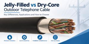
Jelly-Filled vs Dry-Core Outdoor Telephone Cable
Jelly-filled vs dry-core is an important construction choice when specifying outdoor telephone cable for telecom distribution networks,...
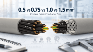
0.5 vs 0.75 vs 1.0 vs 1.5 mm² Control Cable: How to Select Conductor Size
Control cable conductor size affects resistance, voltage drop, current-carrying capability, cable diameter, flexibility and cost. Among...

300/500 V vs 450/750 V Control Cable: When Is the Higher Voltage Rating Required?
Control cable voltage rating is one of the most important electrical parameters to check when selecting cables for industrial machinery...


