





 President’s Message
Blog
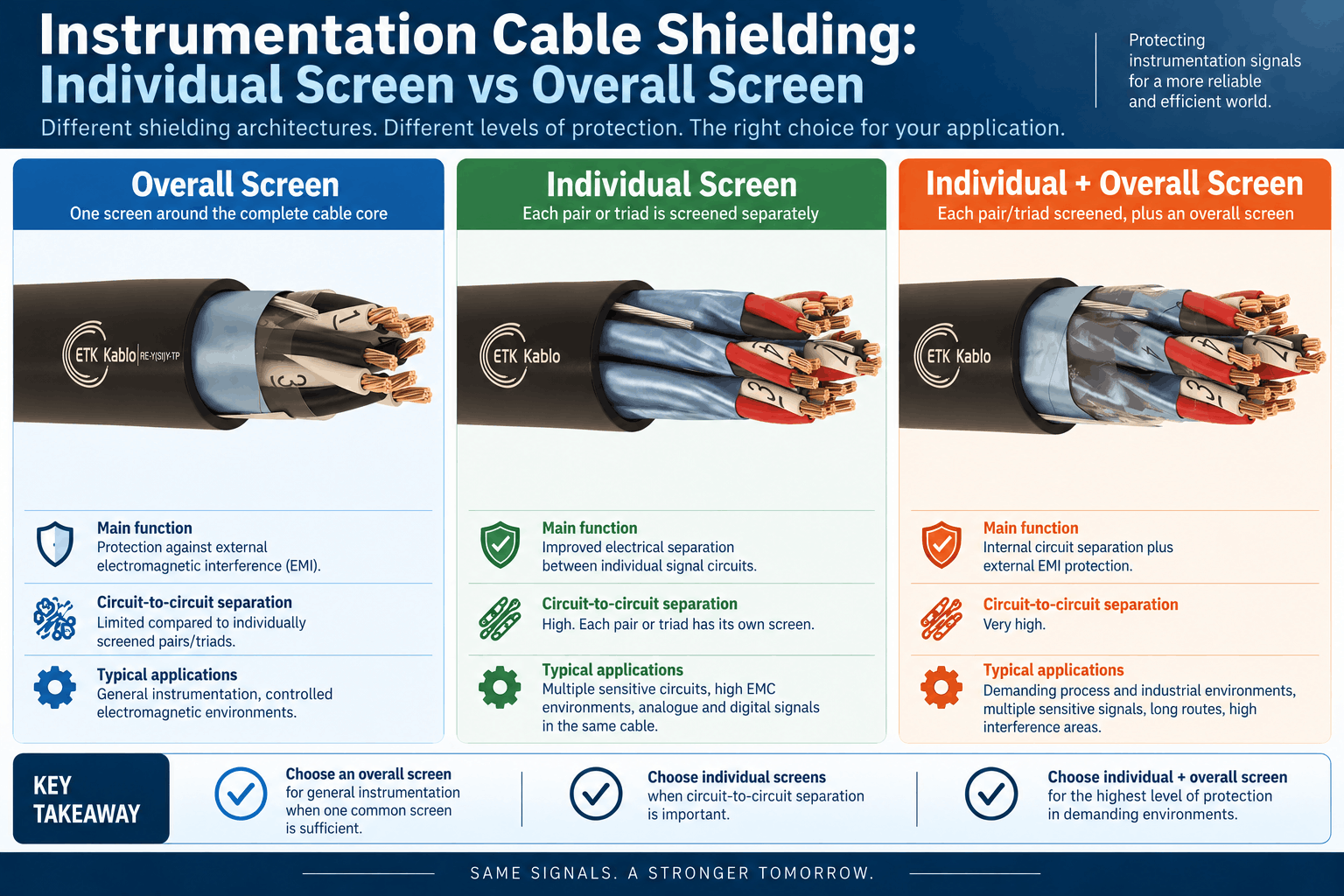
Instrumentation Cable Shielding: Individual Screen vs Overall Screen
Reading Time: 12 minutes
Instrumentation cable shielding plays a critical role in protecting low-level analogue and digital signals from electromagnetic interference and unwanted interaction between circuits. However, not all screened instrumentation cables use the same shielding architecture.
Some cables use a single overall screen around the complete cable core. Others individually screen each pair or triad. More demanding constructions can combine individual pair or triad screens with an additional overall screen.
The correct choice depends on the type of signals being transmitted, the number of circuits sharing the cable, electromagnetic conditions, cable routing, project EMC requirements and the level of separation required between individual instrumentation loops.
Quick answer: An overall screen primarily protects the complete cable core from external electromagnetic interference. Individual pair or triad screens provide additional electrical separation between circuits inside the same cable. When a project combines sensitive signals, multiple instrument loops and a demanding EMI environment, individual screens plus an overall screen may provide the most comprehensive shielding architecture.
Instrumentation Cable Shielding: Individual vs Overall Screen at a Glance
| Shielding Type | Screen Location | Main Purpose | Circuit-to-Circuit Separation | Typical Selection Logic |
|---|---|---|---|---|
| Overall Screen | Around the complete cable core | Protection against external electromagnetic interference | Limited compared with individually screened elements | General instrumentation where one common screen is sufficient |
| Individual Screen | Around each pair or triad | Improved separation between individual signal circuits | High | Multiple sensitive circuits sharing one cable |
| Individual + Overall Screen | Around each pair/triad plus around complete cable core | Internal circuit separation plus external EMI protection | Very high | Demanding process, industrial and high-interference environments |
The important point is that individual and overall screens solve related but different electromagnetic problems.
Therefore, specifying “screened instrumentation cable” without defining the screening arrangement can leave an important technical requirement unclear.
What Is an Overall Screen in an Instrumentation Cable?
An overall screen surrounds the complete assembled cable core rather than each individual pair or triad.
In a typical overall-screened instrumentation cable, the insulated conductors are first arranged into the required pairs, triads or cable core. A metallic screen is then applied around the assembled elements.
Depending on the cable design, this screen may use:
- Aluminum/polyester foil
- Copper braid
- Foil combined with braid
- A metallic tape construction
- A drain or earth wire in contact with the metallic screen
The screen forms a common electromagnetic barrier around all signal elements contained within the cable.
What Does an Overall Screen Protect Against?
The main purpose of the overall screen is to reduce the influence of electromagnetic fields originating outside the cable.
Potential sources of interference in industrial environments can include:
- Power cables
- Motors
- Variable-frequency drives
- Transformers
- Switchgear
- Power converters
- Industrial machinery
- Radio-frequency equipment
- Electrical switching devices
The overall screen provides a conductive barrier around the cable core and helps reduce unwanted electromagnetic coupling into the instrumentation circuits.
When Is an Overall Screen Often Sufficient?
An overall-screened cable can be a practical solution when:
- Signals have similar characteristics
- The project does not require individual circuit screening
- Pair-to-pair interference risk is relatively low
- The cable route has controlled electromagnetic conditions
- Signals are grouped according to an established project philosophy
- The specification specifically calls for collective or overall screening
For many process-control applications, an overall-screened instrumentation cable provides the necessary balance between EMI protection, cable diameter, weight and complexity.
What Is an Individually Screened Instrumentation Cable?
In an individually screened cable, each functional signal element receives its own metallic screen before the screened elements are assembled into the complete cable core.
For pair-based cables, each pair can be individually screened.
For triad-based constructions, each triad can receive its own screen.
This creates an electromagnetic barrier between neighbouring circuits rather than relying only on a screen around the entire cable.
What Does an Individual Screen Do?
An individual screen helps reduce electromagnetic interaction between separate signal elements inside the same cable.
This becomes valuable when several independent instrumentation loops share one multi-pair or multi-triad cable.
For example, one cable might contain signals associated with:
- Pressure transmitters
- Flow transmitters
- Temperature measurements
- Level instruments
- Control valves
- Process monitoring circuits
- DCS inputs and outputs
- PLC signal circuits
Individually screening these circuits provides greater electrical separation between them.
Individual Screen vs Overall Screen: What Is the Main Difference?
The easiest way to understand the difference is to identify the source of interference that the screen is intended to control.
Overall screen: primarily protects the group of circuits from electromagnetic influence outside the cable.
Individual screen: provides additional separation between the different circuits inside the cable.
| EMI Concern | Overall Screen | Individual Screen |
|---|---|---|
| External electrical noise | Strong primary function | Can contribute, depending on construction |
| Interaction between pairs or triads | Limited internal separation | Strong primary function |
| Multiple sensitive signals in one cable | May be adequate depending on project | Often advantageous |
| Cable complexity | Lower | Higher |
| Cable diameter | Generally smaller for comparable designs | Can be larger |
| Termination complexity | Generally simpler | More screens must be managed |
Neither approach is universally superior.
The correct construction depends on what the project needs the screening system to achieve.
What Are PiMF and TiMF Instrumentation Cables?
The terms PiMF and TiMF are commonly used to identify instrumentation cable constructions with individually screened signal elements.
PiMF refers to pairs individually screened with metallic foil.
TiMF applies the same concept to individually screened triads.
In these constructions, the conductors first form a pair or triad. A metallic foil screen and associated earth or drain wire can then be applied around each individual element.
The screened elements are subsequently assembled together to form the complete cable core.
Some cable constructions stop at this stage, while others add another overall screen around the assembled individually screened pairs or triads.
Why Combine Individual Screens with an Overall Screen?
A cable with individual screens and an overall screen addresses two different EMC objectives simultaneously.
The individual screens provide separation between neighbouring signal circuits.
The overall screen provides another barrier between the complete cable core and external electromagnetic interference.
This architecture can be particularly valuable where:
- Many sensitive circuits share one cable
- The installation environment contains significant EMI
- Signal integrity requirements are demanding
- Analogue measurement signals must remain well separated
- Project specifications require individual and collective screening
- Long instrumentation routes pass through industrial areas
However, the additional shielding also increases the construction complexity of the cable.
Therefore, individual plus overall screening should be selected because the project requires the additional electrical separation rather than simply because it represents the most elaborate cable design.
Overall-Screened vs PiMF/TiMF Instrumentation Cable
| Characteristic | Overall-Screened Cable | PiMF / TiMF Cable with Individual Screens |
|---|---|---|
| Common external screen | Yes | May also be included |
| Screen around each pair/triad | No | Yes |
| External EMI protection | Primary purpose | Strong when combined with overall screen |
| Pair-to-pair / triad-to-triad separation | Lower | Higher |
| Cable construction complexity | Lower | Higher |
| Termination complexity | Lower | Higher |
| Typical use | General process instrumentation | Sensitive multi-circuit instrumentation systems |
Does Individual Screening Improve Signal Quality?
Individual screening can improve signal isolation where interference between circuits would otherwise become significant.
However, it is important to avoid oversimplifying the relationship between shielding and signal quality.
Instrumentation signal performance also depends on:
- Pair or triad twisting
- Conductor geometry
- Mutual capacitance
- Capacitance unbalance
- Conductor resistance
- Signal level
- Cable length
- Grounding philosophy
- Termination
- Installation route
- Separation from power circuits
A poorly installed individually screened cable cannot compensate for every other design problem in an instrumentation system.
Screening should therefore be considered as one part of the complete signal-integrity strategy.
Does an Overall Screen Prevent Crosstalk Between Pairs?
An overall screen surrounds the complete cable core, so it does not physically isolate one pair from another in the same way as individual screens.
Pair twisting and cable-element design already provide an important level of internal signal separation.
However, where a project requires stronger isolation between multiple circuits, individually screened pairs or triads can provide an additional electromagnetic barrier.
This is why multi-pair instrumentation cables carrying highly sensitive or dissimilar signals may use individual screening rather than relying exclusively on a common overall screen.
When Should You Choose an Overall-Screened Instrumentation Cable?
An overall-screened construction can be considered where:
- The circuits have similar signal characteristics
- The project standard permits collective screening
- External EMI is the primary screening concern
- Individual circuit isolation is not required
- A simpler cable construction is preferred
- Cable diameter and termination efficiency are important
- The instrumentation cable schedule specifies overall screening
Common ETK cable constructions such as RE-2X(St)H, RE-2X(St)Y, RE-2X(St)HSWAH and RE-2X(St)YSWAY can use an overall Al/PET screen depending on the specific product design.
These constructions can provide screened analogue and digital signal transmission without individually screening every pair or triad.
When Should You Choose Individually Screened Pairs or Triads?
Individual screening becomes more attractive when:
- Many instrumentation circuits share one cable
- Signals are particularly sensitive
- Circuit-to-circuit isolation is important
- Different types of signals must be routed together
- The project specification requires PiMF or TiMF construction
- Process measurements require additional noise protection
- EMC conditions are demanding
For these projects, individual pair or triad screens can reduce electromagnetic interaction between the separate instrument circuits.
When Should You Specify Individual and Overall Screening Together?
A combined construction may be appropriate when the project has both significant external interference and demanding internal circuit-isolation requirements.
| Project Condition | Screening Architecture to Consider |
|---|---|
| General instrumentation in controlled EMI environment | Overall screen |
| Multiple sensitive circuits in one cable | Individual screens |
| High external EMI plus sensitive multi-circuit signals | Individual + overall screen |
| Project explicitly specifies PiMF / TiMF plus collective screen | Individual + overall screen |
| Simple protected industrial signal route | Overall screen may be sufficient |
This table provides selection logic rather than a universal engineering rule.
The final choice should follow the instrument loop requirements, project EMC philosophy and applicable specification.
Individual Screen vs Overall Screen for Oil and Gas Projects
Oil, gas and petrochemical facilities provide a good example of why screening decisions should be made circuit by circuit rather than by industry name alone.
A refinery may contain:
- Low-level analogue signals
- Digital instrumentation circuits
- Emergency shutdown systems
- DCS networks
- Process measurement loops
- Motors and variable-frequency drives
- High-current power distribution
These circuits create different electromagnetic environments across the plant.
An overall-screened cable may be entirely suitable for one instrument route, while individually screened PiMF or TiMF construction may be justified for another.
The correct specification therefore depends on the actual circuit grouping and cable route.
Individual Screen vs Overall Screen for DCS and PLC Systems
DCS and PLC systems can contain large numbers of field signals connected to centralized control equipment.
The screening requirement should be determined by:
- Signal type
- Input/output architecture
- Number of circuits per cable
- Analogue or digital transmission
- Signal level
- Route length
- EMI environment
- Control-system manufacturer requirements
For a multi-pair cable carrying several sensitive analogue instrument loops, individual screening may provide useful circuit separation.
For less sensitive grouped circuits in a controlled environment, an overall screen may meet the project requirement more efficiently.
What Is the Role of the Drain or Earth Wire?
Foil-screened instrumentation cables commonly include a tinned copper drain or earth wire in electrical contact with the metallic side of the screen.
This conductor provides a practical means of connecting the foil screen to the intended grounding or bonding system.
In an individually screened cable, each screened pair or triad may have its own associated earth wire.
A cable with an additional overall screen may also include a separate earth wire for the common screen.
The exact screen-termination method should follow the project EMC and grounding philosophy.
Should an Instrumentation Cable Screen Be Grounded at One End or Both Ends?
There is no universal answer that applies to every instrumentation system.
Screen-earthing arrangements depend on:
- Signal type
- Frequency
- Equipment design
- Potential differences between grounding points
- Hazardous-area requirements
- Control-system manufacturer instructions
- Project EMC philosophy
For some low-frequency analogue instrumentation circuits, project practices may specify screen termination at one end to reduce unwanted circulating currents.
Other systems or higher-frequency EMC requirements can use different bonding arrangements.
Therefore, the cable manufacturer should provide a cable with the required screen construction, while the system designer determines how the screen is terminated within the installation.
Does Steel Wire Armour Replace the Instrumentation Screen?
No.
Steel wire armour and an instrumentation screen perform different primary functions.
The instrumentation screen is selected for electromagnetic performance.
Steel wire armour is primarily selected for mechanical protection.
An armored instrumentation cable can therefore contain:
- Individual screens
- An overall screen
- Individual plus overall screens
- Steel wire armour outside the screened cable core
For example, an SWA cable may use a dedicated Al/PET foil screen to protect instrumentation signals while galvanized steel wires provide the mechanical protection required by the installation.
Armour should not be treated as a substitute for the specified signal screen.
Does Individual Screening Mean the Cable Must Be Armored?
No.
Screening and armouring are independent cable-design decisions.
A PiMF or TiMF instrumentation cable can be:
- Unarmored
- Steel wire armored
- Halogen-free
- PVC-sheathed
- Fire resistant
- Standard flame-retardant
The screen architecture is selected according to electromagnetic requirements.
The armour is selected according to mechanical requirements.
The sheath and fire-performance characteristics are selected according to environmental and fire-safety requirements.
Does Individual Screening Increase Cable Size?
Generally, adding screens around each pair or triad introduces additional materials into the cable construction.
Depending on the number of elements and the cable design, this can increase:
- Overall cable diameter
- Cable weight
- Material content
- Termination time
- Installation complexity
- Cost
This does not mean individual screening is undesirable.
It means the additional construction should solve a real technical requirement.
If the project only requires protection against external EMI and the internal circuit grouping is straightforward, an overall-screened cable can provide a more efficient design.
Are More Screens Always Better?
No.
More metallic screening can provide additional electromagnetic separation, but it also creates more complex cable construction and installation requirements.
The correct objective is not to maximize the amount of metal in the cable.
The objective is to achieve the required signal integrity with an appropriate, technically justified construction.
Over-specification can increase:
- Cable diameter
- Drum weight
- Installation effort
- Gland size
- Termination labour
- Project cost
Therefore, engineers should determine the required screening architecture before selecting the cable.
EN 50288-7 and Instrumentation Cable Screening
EN 50288-7 is an important reference for multi-element metallic instrumentation and control cables used for analogue and digital communication and control signals in industrial environments.
The standard recognizes screening both at the level of individual cable elements and around the complete cable core.
Depending on the required design, metallic screens can use constructions such as:
- Metal braid
- Foil
- Foil combined with braid
- Foil with a drain wire
This illustrates why “screened according to EN 50288-7” does not necessarily describe one universal screen arrangement.
The project specification must still identify whether the cable requires:
- Overall screening
- Individual pair screening
- Individual triad screening
- Individual and overall screening
How Should Instrumentation Cable Shielding Be Specified in an RFQ?
A procurement request should avoid ambiguous descriptions such as:
“20 pair screened instrumentation cable.”
Instead, the buyer should identify exactly how the screen is intended to be applied.
A technically useful RFQ may define:
- Number of pairs or triads
- Conductor cross-section
- Individual screening requirement
- PiMF or TiMF construction where required
- Overall screening requirement
- Screen material
- Drain or earth wire requirement
- Insulation material
- Operating voltage
- Mutual capacitance requirement
- Armour requirement
- PVC or halogen-free sheath
- Indoor or outdoor use
- Fire-performance requirements
- Applicable manufacturing standard
- Required testing documentation
For example, instead of requesting:
“12 pair screened instrumentation cable.”
the project could specify:
“12-pair instrumentation cable with individually Al/PET-screened pairs, individual drain wires and an additional overall Al/PET screen with overall earth wire.”
The second description communicates the electromagnetic construction much more clearly.
Common Mistakes When Specifying Instrumentation Cable Shielding
1. Using the Word “Screened” Without Defining the Screen Location
A screen around the complete cable and a screen around every pair are not the same construction.
The RFQ should identify individual, overall or combined screening.
2. Assuming an Overall Screen Provides the Same Pair Isolation as PiMF
An overall screen surrounds all elements together. It does not create a metallic barrier around each individual pair.
3. Specifying PiMF When the Cable Uses Triads
PiMF refers to individually screened pairs. Where three-conductor functional elements are required, TiMF terminology may be more appropriate.
4. Treating Armour as the Signal Screen
SWA primarily provides mechanical protection and should not replace the dedicated instrumentation screen required by the cable specification.
5. Assuming More Screening Automatically Improves Every Circuit
Screening must match the actual EMC problem. Additional screens can create unnecessary size, cost and termination complexity when they provide no meaningful project benefit.
6. Ignoring Screen Termination
The physical cable screen cannot perform as intended if the installation does not follow the required grounding and bonding philosophy.
7. Ignoring Cable Capacitance
Individual screens can affect cable construction and electrical parameters. For sensitive or intrinsically safe circuits, the complete capacitance and inductance requirements should also be reviewed.
8. Mixing Signal Types Without Reviewing the Project Philosophy
Different signal types may require separation or dedicated screening arrangements. Engineers should not assume that every signal can share the same multi-pair cable simply because each pair is screened.
Which Instrumentation Cable Shielding Should You Choose?
| Requirement | Screening to Consider | Reason |
|---|---|---|
| General instrumentation signals in controlled environment | Overall screen | Efficient protection against external EMI |
| Multiple sensitive analogue circuits | Individual pair screens | Provides stronger circuit-to-circuit isolation |
| Triad-based sensitive signals | Individual triad screens | Provides separation between individual triad circuits |
| High EMI plus multiple sensitive signals | Individual + overall screen | Combines internal isolation with external EMI protection |
| Mechanically exposed route | Required screen architecture + armour | EMI protection and mechanical protection are separate requirements |
| Project explicitly specifies PiMF/TiMF | Individual screens as specified | Ensures each signal element receives its own screen |
The final choice should always follow the instrumentation philosophy and project specification.
ETK Kablo Overall and Individually Screened Instrumentation Cables
ETK Kablo manufactures a broad range of instrumentation cable shielding constructions for industrial automation, process control, measurement systems, oil and gas facilities, petrochemical projects and infrastructure applications.
Overall-screened cable families include constructions such as RE-2X(St)H, RE-2X(St)Y, RE-2X(St)HSWAH and RE-2X(St)YSWAY, where an Al/PET screen with a tinned copper earth wire protects the assembled cable core.
For projects requiring greater separation between individual instrument circuits, ETK Kablo also manufactures PiMF and TiMF constructions with individually screened pairs or triads.
Selected PiMF/TiMF cable families combine individual Al/PET screens and individual earth wires with an additional overall Al/PET screen, providing both circuit-to-circuit separation and protection against external electromagnetic interference.
These individual-screen constructions are also available in different physical cable designs depending on project requirements, including PVC, halogen-free, unarmored and steel wire armored options.
The appropriate cable should therefore be selected according to both the electrical screening requirement and the physical installation conditions.
Frequently Asked Questions
What is instrumentation cable shielding?
Instrumentation cable shielding uses metallic foil, braid or another conductive screen to reduce unwanted electromagnetic coupling into or between sensitive analogue and digital signal circuits.
What is the difference between individual screen and overall screen?
An overall screen surrounds the complete cable core and primarily protects the grouped circuits from external electromagnetic interference. An individual screen surrounds each pair or triad separately and provides additional separation between circuits inside the cable.
What is an overall screened instrumentation cable?
An overall screened instrumentation cable uses one common metallic screen around all assembled signal elements. The screen commonly includes foil or braid and may use a drain or earth wire for termination.
What is an individually screened instrumentation cable?
An individually screened instrumentation cable applies a metallic screen around each functional pair or triad before the elements are assembled into the complete cable.
What does PiMF mean?
PiMF refers to pairs individually screened with metallic foil. Each pair receives its own screen, improving electrical separation between individual signal circuits.
What does TiMF mean?
TiMF refers to triads individually screened with metallic foil. The principle is similar to PiMF but applies to three-conductor signal elements.
Can an instrumentation cable have both individual and overall screens?
Yes. Individually screened pairs or triads can be assembled together and then covered by an additional overall screen. This provides both internal circuit separation and external EMI protection.
Is an individually screened cable always better?
No. Individual screening provides additional circuit isolation but also increases cable complexity, size and termination requirements. An overall-screened cable may be fully adequate where the project does not require individual circuit screening.
Does steel wire armour provide EMI shielding?
Steel wire armour is primarily a mechanical protection layer. Instrumentation cables should use the dedicated foil or braid screen specified for their electromagnetic performance rather than relying on armour as a replacement.
Should an instrumentation cable screen be grounded?
Screen termination should follow the project grounding and EMC philosophy. The correct arrangement can vary according to signal type, equipment, hazardous-area requirements and system design.
Which shielding is best for oil and gas instrumentation cables?
There is no single shielding architecture for every oil and gas circuit. Overall screening can suit many general process signals, while PiMF or TiMF constructions may be selected where greater isolation between sensitive circuits is required.
Does EN 50288-7 allow individual and overall screens?
Yes. EN 50288-7 includes provisions for screening individual cable elements as well as screening the complete cable core, depending on the specified cable design.
Conclusion
Selecting the correct instrumentation cable shielding begins by identifying what type of electromagnetic interference the cable must control.
An overall screen provides a common barrier around the complete cable core and is an efficient solution for many general instrumentation applications where external EMI is the main concern.
Individual screens around pairs or triads provide an additional level of separation between circuits, making PiMF and TiMF constructions particularly valuable where multiple sensitive signals share one cable.
For demanding environments, both approaches can be combined. Individual screens isolate the separate signal elements, while an additional overall screen protects the complete cable core from external electromagnetic influence.
More screening is not automatically better. Each additional screen increases construction complexity, cable diameter and termination requirements.
The most effective specification therefore matches the shielding architecture to the signal type, circuit grouping, electromagnetic environment, grounding philosophy and project requirements rather than simply selecting the cable with the greatest number of metallic layers.
Benzer yazılar
RE-2X(St)H vs RE-2X(St)HSWAH vs RE-2X(St)Y vs RE-2X(St)YSWAY: Which Should You Choose?
Choosing the right RE-2X(St) instrumentation cable is not simply a matter of comparing four similar product codes. RE-2X(St)H, RE-2X(St...
How to Specify Instrumentation Cables for Oil & Gas Projects
Selecting oil and gas instrumentation cables requires much more than choosing a conductor size and adding a screen. Refineries, petroch...


