





 President’s Message
Blog
PiMF vs TiMF Instrumentation Cable Explained
Reading Time: 16 minutes
Understanding PiMF vs TiMF cable construction is important when an instrumentation system carries multiple low-level analogue or digital signals through the same multicircuit cable. Both terms describe individually screened cable elements, but PiMF applies to pairs while TiMF applies to triads.
In a PiMF cable, each twisted pair receives its own metallic screen before the manufacturer assembles the complete cable core. By contrast, a TiMF cable individually screens each three-conductor triad. As a result, both constructions can provide additional electrical separation between neighboring instrumentation circuits compared with a cable that relies only on one common overall screen.
However, PiMF should not automatically be considered better than TiMF, or vice versa. The number of conductors in the field circuit determines whether a pair or triad is appropriate. Individual screening then addresses a separate requirement: electromagnetic interference and circuit-to-circuit coupling.
Quick answer: Choose PiMF when the instrument circuit uses a pair and requires individual screening, such as many noise-sensitive two-wire analogue loops. Choose TiMF when the instrument requires a three-conductor triad and individual screening is also required, such as selected three-wire measurement circuits. For both designs, the project must separately define the overall screen, capacitance, conductor size, armour, sheath material and grounding philosophy.
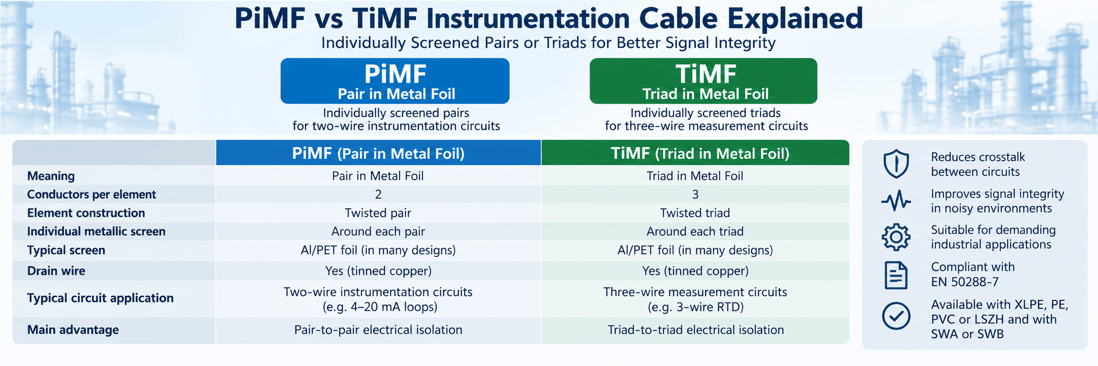
PiMF vs TiMF Cable at a Glance
| Characteristic | PiMF | TiMF |
|---|---|---|
| Meaning | Pair in Metal Foil | Triad in Metal Foil |
| Conductors per screened element | 2 | 3 |
| Element construction | Twisted pair | Twisted triad |
| Individual metallic screen | Around each pair | Around each triad |
| Typical screen | Al/PET foil + drain wire in many designs | Al/PET foil + drain wire in many designs |
| Typical circuit logic | Two-conductor instrumentation circuit | Three-conductor instrumentation circuit |
| Common application example | Noise-sensitive 4–20 mA loop | Noise-sensitive 3-wire measurement circuit |
| Additional overall screen possible? | Yes | Yes |
| Main screening advantage | Pair-to-pair electrical isolation | Triad-to-triad electrical isolation |
| Best selection basis | Two-wire circuit + individual screening requirement | Three-wire circuit + individual screening requirement |
Therefore, PiMF and TiMF are best understood as two versions of the same screening philosophy applied to different cable elements.
What Does PiMF Mean?
PiMF commonly means Pair in Metal Foil.
The manufacturer first twists two insulated conductors together to form an instrumentation pair. Next, the pair receives an individual metallic screen, commonly an aluminium/polyester foil in instrumentation cable designs.
A drain wire may run in direct contact with the conductive side of the foil so that installers can terminate the screen effectively.
Consequently, each pair becomes an electrically screened element before several pairs are assembled into the complete cable.
Typical PiMF Construction
A PiMF instrumentation cable can include:
- Stranded or solid copper conductors
- PE, XLPE, PVC or project-specific insulation
- Twisted conductor pairs
- Individual polyester wrapping where required
- Individual Al/PET foil screen
- Individual drain wire
- Overall cable assembly
- Overall screen where required
- Inner sheath
- Armour where required
- Outer sheath
However, the exact sequence depends on the specific cable family and project specification.
What Does TiMF Mean?
TiMF commonly refers to a Triad in Metal Foil.
Instead of screening two twisted conductors, the manufacturer groups three conductors into a triad and places a metallic screen around that complete three-conductor element.
Therefore, each triad remains electrically separated from neighboring triads before the complete cable core is assembled.
Typical TiMF Construction
A TiMF instrumentation cable can include:
- Copper conductors
- PE, XLPE, PVC or other insulation
- Three conductors twisted as a triad
- Individual wrapping where required
- Individual metallic foil screen
- Drain wire
- Assembly of individually screened triads
- Additional overall screen
- Inner sheath
- Mechanical armour where specified
- Outer sheath
As with PiMF, the individual screen represents only one part of the complete cable construction.
What Is the Main Difference Between PiMF and TiMF?
The fundamental difference is the cable element inside the individual screen.
PiMF = individually screened pair.
TiMF = individually screened triad.
Therefore, a PiMF vs TiMF cable comparison should not be treated primarily as a shielding-performance competition.
Instead, the field circuit determines whether two or three conductors belong together. Once engineers establish that requirement, they can decide whether the individual pair or triad needs its own metallic screen.
PiMF vs TiMF Is Not the Same as Pair vs Triad
This distinction prevents an important specification error.
The terms pair and triad describe conductor grouping.
Meanwhile, PiMF and TiMF indicate that the pair or triad also receives an individual metallic screen.
| Construction | Conductors per Element | Individual Element Screen |
|---|---|---|
| Pair | 2 | No dedicated individual screen unless specified |
| PiMF | 2 | Yes |
| Triad | 3 | No dedicated individual screen unless specified |
| TiMF | 3 | Yes |
Consequently, a project should first answer one question:
Does the circuit require a pair or triad?
Then it should answer another:
Does that element require individual screening?
Why Are Instrumentation Cable Elements Individually Screened?
A multicircuit instrumentation cable can carry many low-level signals within one outer sheath.
Without individual screens, nearby circuits can interact through electric and electromagnetic coupling. Although twisting already helps control interference, sensitive systems can require greater circuit isolation.
For this reason, individual screens can help reduce unwanted coupling between:
- Adjacent analogue loops
- Different transmitter circuits
- Measurement signals
- Control circuits
- Low-level instrumentation signals
Meanwhile, an overall screen can provide another layer of protection against interference entering from outside the cable.
Individual Screen vs Overall Screen
An individual screen and an overall screen perform related but different functions.
Individual screen: surrounds one pair or triad.
Overall screen: surrounds the complete assembled cable core.
| Screen Type | Main Location | Primary Purpose |
|---|---|---|
| Individual pair screen | Around each pair | Additional pair-to-pair isolation |
| Individual triad screen | Around each triad | Additional triad-to-triad isolation |
| Overall screen | Around all cable elements | Protection against external electromagnetic influence |
| Individual + overall screen | Both levels | Combines circuit isolation with external screening |
Therefore, a PiMF or TiMF cable can still include an overall screen.
In demanding instrumentation networks, manufacturers often combine both screening levels.
Why Use Both Individual and Overall Screens?
Using two screening levels addresses two different interference paths.
First, the individual foil screen helps isolate one instrumentation element from neighboring elements inside the cable.
Second, the overall screen helps shield the complete cable core from external electrical noise.
As a result, an individually and overall-screened construction can be attractive in environments containing:
- Motors
- Variable-frequency drives
- Power converters
- Transformers
- Switchgear
- High-current power cables
- Industrial machinery
However, additional screening increases cable diameter, material content and termination complexity. Therefore, engineers should use it where the signal environment justifies the additional construction.
PiMF Cable for 4–20 mA Loops
Many 4–20 mA transmitter circuits use two conductors.
Consequently, a pair provides the natural electrical element. Where the project also requires individual screening, PiMF becomes a logical construction.
Potential applications include:
- Pressure transmitters
- Flow transmitters
- Level transmitters
- Temperature transmitters
- Process analyzers
- Other two-wire analogue instrumentation
However, not every 4–20 mA installation requires individually screened pairs. The decision depends on circuit density, route length, EMC conditions and project philosophy.
TiMF Cable for Three-Wire Measurement Circuits
Some instrumentation circuits require three related conductors.
For example, certain 3-wire RTD measurement circuits use three conductors that belong to the same measurement system.
If the project also requires individual screening, TiMF keeps all three conductors inside one dedicated screen.
Therefore, TiMF can provide an organized solution for three-wire measurement circuits in electrically demanding plants.
Does TiMF Provide Better Screening Than PiMF?
No, not simply because it contains three conductors.
The number of conductors inside the foil does not automatically determine screening effectiveness.
Instead, screening performance depends on factors such as:
- Screen material
- Foil overlap
- Drain-wire arrangement
- Screen continuity
- Overall cable geometry
- Frequency of the interference
- Termination quality
- Grounding and bonding method
Therefore, TiMF should be chosen because the circuit requires a triad, not because the engineer assumes that three conductors provide stronger EMI protection.
Does PiMF Provide Better Screening Than an Unscreened Pair?
PiMF adds a dedicated metallic barrier around each pair. Therefore, it can provide additional electrical isolation compared with an equivalent pair construction without an individual screen.
However, the installed system still depends on proper:
- Cable routing
- Screen termination
- Grounding
- Separation from power circuits
- Equipment design
Consequently, PiMF should form part of the overall EMC strategy rather than serve as a substitute for good system engineering.
What Is the Drain Wire in PiMF and TiMF Cable?
A foil screen needs a practical means of electrical connection.
For this reason, many instrumentation cable designs place a tinned-copper drain wire in contact with the metallic side of the foil.
The drain wire provides an accessible conductor for screen termination.
Depending on the cable design, the cable can include:
- One drain wire for every individually screened pair
- One drain wire for every individually screened triad
- An additional drain wire for the overall screen
However, exact screen and drain-wire construction should always be confirmed from the product datasheet.
Why Is Aluminium/Polyester Foil Commonly Used?
Aluminium/polyester laminated foil provides a lightweight and compact screening layer.
It can offer high coverage around an instrumentation pair or triad without adding the diameter and weight associated with a heavy braid.
Therefore, foil screening works particularly well in multicircuit instrumentation cables where manufacturers must screen many individual elements within one overall cable.
Nevertheless, metallic braid and foil-plus-braid systems can also be used where the project or cable standard requires them.
Foil Screen vs Braid Screen
| Characteristic | Foil Screen | Braid Screen |
|---|---|---|
| Coverage | Can provide very high coverage | Depends on braid filling factor |
| Diameter | Compact | Generally larger |
| Weight | Lower | Higher |
| Mechanical robustness | Lower than heavy braid | Strong |
| Termination | Commonly uses drain wire | Braid itself can provide conductive termination |
| Typical individual instrumentation screen | Very common | Possible depending on specification |
Therefore, PiMF and TiMF should not be interpreted as requiring only one universal foil construction across every manufacturer.
EN 50288-7 and Individual Cable Element Screening
EN 50288-7 provides an important framework for multi-element instrumentation and control cables used for analogue and digital signal transmission.
The standard recognizes individual screening of cable elements and allows several metallic-screen constructions.
Depending on the required design, individual element screens can use:
- Metal braid
- Foil + braid
- Foil with an associated drain wire
Therefore, PiMF and TiMF terminology describes a common instrumentation-cable architecture, while the exact screening construction should follow the relevant product specification.
PiMF vs TiMF Cable and Crosstalk
Crosstalk describes unwanted coupling from one circuit into another.
In large instrumentation cables, many signal elements run parallel for substantial distances. Consequently, designers may need to control interaction between neighboring circuits.
Individual screens can reduce this coupling by placing a conductive barrier around each circuit element.
For this reason, PiMF and TiMF designs can be particularly useful in high-density instrumentation systems.
PiMF vs TiMF Cable and Signal Integrity
Signal integrity depends on the complete electrical circuit rather than screening alone.
Important factors include:
- Conductor resistance
- Capacitance
- Inductance
- Twist length
- Screening
- Route length
- Signal type
- Equipment characteristics
Therefore, the presence of PiMF or TiMF does not automatically guarantee that every analogue or digital signal will operate correctly.
Instead, individual screening forms one part of the transmission design.
PiMF vs TiMF Cable and Capacitance
The metallic screen changes the electrical relationship between conductors and their surroundings.
Consequently, individually screened instrumentation cable can have different capacitance characteristics from an otherwise similar construction without individual screens.
Important parameters can include:
- Mutual capacitance
- Conductor-to-screen capacitance
- Capacitance unbalance
Therefore, engineers working with long circuits or sensitive systems should verify actual datasheet values rather than selecting cable only by the PiMF or TiMF designation.
PiMF and TiMF in Intrinsically Safe Circuits
Intrinsic safety places limits on the electrical energy that can enter a hazardous area.
For this reason, cable capacitance and inductance can contribute to the complete safety calculation.
A PiMF or TiMF construction can provide useful circuit segregation, but the designation itself does not establish intrinsic-safety compliance.
Instead, engineers must evaluate:
- Cable capacitance
- Cable inductance
- Loop length
- Barrier or isolator parameters
- Field-device parameters
- Applicable hazardous-area requirements
Consequently, individual screening should be treated as one cable characteristic within the full intrinsically safe loop calculation.
Does PiMF or TiMF Require a Blue Sheath?
No.
Blue is sometimes used as a project identification colour for intrinsically safe circuits.
However, PiMF and TiMF describe the internal screening arrangement, not the outer-sheath colour.
Therefore, either construction can use different sheath colours according to the cable family and project requirements.
PiMF vs TiMF with XLPE Insulation
Individual screening can be combined with different insulation systems.
XLPE provides strong electrical characteristics together with increased thermal and mechanical performance compared with many conventional thermoplastic insulation systems.
Therefore, XLPE-based PiMF and TiMF constructions can be suitable for demanding process-control applications.
However, insulation choice remains independent from whether the cable uses pairs or triads.
PiMF vs TiMF with PE Insulation
PE is also widely used in instrumentation cables because of its electrical insulation characteristics.
For example, PE can be attractive where projects place particular emphasis on insulation resistance and electrical transmission characteristics.
Again, both PiMF and TiMF designs can use suitable PE insulation according to the required cable specification.
PiMF vs TiMF with PVC or LSZH Sheath
The outer jacket forms another separate design choice.
PiMF and TiMF cables can use:
- PVC outer sheath
- LSZH outer sheath
- PE outer sheath
- Other specialized compounds
Therefore, the screening acronym does not define fire performance.
For example, a PiMF cable can use PVC in a conventional industrial environment, while another PiMF cable can use a halogen-free sheath for an enclosed or evacuation-sensitive installation.
PiMF vs TiMF with Steel Wire Armour
Individual screening and mechanical armour solve completely different problems.
PiMF or TiMF protects the individual electrical circuit against unwanted coupling and electromagnetic interference.
Meanwhile, Steel Wire Armour protects the complete cable against mechanical stress.
Therefore, an armored instrumentation cable can combine:
- PiMF or TiMF individual screening
- Overall screen
- Inner sheath
- SWA
- Outer sheath
This construction can be particularly useful in mechanically demanding industrial and oil-and-gas routes.
PiMF vs TiMF with Steel Wire Braid
Similarly, SWB can provide additional mechanical reinforcement where a project requires a different balance between protection and flexibility.
The individual screening architecture remains unchanged.
Consequently, projects should define shielding and armour independently.
PiMF and TiMF for Oil and Gas Projects
Oil and gas facilities represent a major application for individually screened instrumentation cables.
These projects can contain:
- Thousands of analogue loops
- Process transmitters
- RTDs
- Control valves
- Shutdown systems
- Analyzers
- Motors and drives
- High-voltage equipment
As a result, signal cables can share trays and routes with numerous potential sources of electrical noise.
PiMF can provide individual screening for pair-based circuits, while TiMF performs the equivalent role for triad-based circuits.
PiMF and TiMF for Refineries
Refineries combine long cable routes with dense analogue and digital instrumentation.
Therefore, project specifications may require individually screened elements to reduce interaction between circuits.
In addition, the same cable may require:
- SWA
- UV resistance
- Oil resistance
- Hydrocarbon resistance
- LSZH performance
- Flame retardancy
Consequently, PiMF/TiMF should form one line within the complete instrumentation cable specification rather than define the entire cable.
PiMF and TiMF for Petrochemical Plants
Petrochemical networks often carry sensitive measurement signals over long distances between field equipment and control systems.
For this reason, individually screened instrumentation elements can be useful where multiple circuits share one multicircuit cable.
However, designers should still coordinate:
- Instrument type
- Signal level
- Screen termination
- Intrinsic safety
- Cable routing
- Armour
- Environmental protection
PiMF and TiMF for Power Plants
Power plants contain generators, transformers, motors and switching equipment that can create significant electromagnetic environments.
Therefore, individual screening may provide useful isolation for low-level measurement circuits.
Nevertheless, a two-wire instrument should still use a pair-based construction, while a three-wire instrument should use an appropriate triad when required.
In other words, EMI severity influences the need for screening, not the number of conductors in the circuit.
PiMF and TiMF for Industrial Automation
Industrial automation can combine analogue measurements, discrete control and digital communications within one facility.
Individually screened cable elements can be useful for:
- Remote process transmitters
- Analogue I/O
- Temperature measurement
- Control systems
- Monitoring equipment
However, dedicated digital buses can require specific impedance or transmission characteristics that a generic PiMF or TiMF instrumentation cable may not provide.
Therefore, protocol requirements should always be checked separately.
Can PiMF or TiMF Be Used for Digital Communication?
Potentially, but the screening acronym alone does not establish compatibility.
A digital communication system can require specific:
- Characteristic impedance
- Capacitance
- Attenuation
- Maximum distance
- Twist geometry
- Termination
Consequently, engineers should select cable according to the protocol specification rather than assuming that individually screened instrumentation cable automatically supports every digital network.
PiMF vs TiMF and Screen Grounding
Screen grounding deserves careful attention because an incorrectly implemented screen can fail to deliver the expected EMC benefit.
The project grounding philosophy can depend on:
- Signal type
- Instrument manufacturer requirements
- Hazardous-area philosophy
- Control-system design
- Potential differences between locations
- EMC practice
Therefore, cable manufacturers should not prescribe one universal grounding arrangement for every PiMF or TiMF installation.
The project engineer and system designer should define the termination method.
Should Individual Screens Be Connected at Both Ends?
There is no universal answer that applies to every instrumentation circuit.
Grounding screens at one end or multiple points can have different consequences depending on frequency, equipment design and grounding-system potential.
Therefore, installers should follow the approved project EMC and grounding philosophy rather than applying a generic cable rule.
What Happens If Individual Screen Continuity Is Lost?
An individual screen works most effectively when its conductive path remains continuous through the intended cable segment and termination system.
Damage or poor termination can reduce the screen’s effectiveness.
For this reason, field installation should preserve:
- Foil integrity
- Drain-wire continuity
- Correct gland entry
- Specified grounding arrangement
- Separation between independent screens
Consequently, the installation quality matters almost as much as the cable construction.
PiMF vs TiMF and Junction Boxes
Individually screened cable can create more termination work inside junction boxes.
Each pair or triad can have its own drain wire and screen treatment.
Therefore, designers should consider:
- Terminal density
- Screen bars
- Junction-box size
- Cable gland dimensions
- Maintenance access
In large instrumentation systems, these practical details can materially affect installation time.
PiMF vs TiMF and Cable Diameter
Individual screening adds foil, drain wires and wrapping materials to every cable element.
Consequently, a PiMF or TiMF cable can have a larger diameter than a similar overall-screen-only construction.
TiMF can also require more space than an equivalent pair-based design because each triad contains three conductors.
Therefore, tray capacity, gland size and minimum bending radius should be checked from the actual datasheet.
PiMF vs TiMF and Cable Weight
More conductors and additional metallic screens increase material content.
As a result, individually screened cables can have higher weight than simpler instrumentation designs.
This affects:
- Drum handling
- Transport
- Cable tray loading
- Pulling effort
- Installation labour
Nevertheless, the additional construction can be justified where circuit isolation and EMC performance matter.
When Is PiMF the Better Choice?
PiMF should be considered when:
- The field circuit uses two conductors
- Several signal pairs share one multicircuit cable
- Circuit-to-circuit isolation is important
- The installation has significant electrical noise
- The project specification requires individually screened pairs
- The electrical parameters meet the signal-system requirements
For example, individually screened multipair cable can provide an effective architecture for large groups of analogue transmitter loops.
When Is TiMF the Better Choice?
TiMF should be considered when:
- The instrument requires three related conductors
- Several three-wire circuits share one cable
- Individual triad screening is required
- The project requires additional circuit isolation
- The cable’s electrical characteristics meet the measurement-system requirements
For example, individually screened multitriad construction can provide a logical solution for multiple three-wire measurement circuits.
When Is Overall Screening Alone Enough?
Not every instrumentation network requires PiMF or TiMF.
An overall-screen-only construction can be sufficient when:
- Signals are relatively robust
- Circuit-to-circuit coupling risk is low
- EMI conditions are controlled
- Cable routes are well separated from power circuits
- The project specification does not require individual screens
Therefore, individually screening every circuit can represent unnecessary cost and cable size in some installations.
Which Construction Should You Choose?
| Project Requirement | Construction to Consider | Reason |
|---|---|---|
| Two-wire circuit, moderate EMI | Overall-screened pair cable | Simple and efficient where individual isolation is unnecessary |
| Two-wire circuit, higher isolation requirement | PiMF | Individual screen around each pair |
| Three-wire circuit, moderate EMI | Overall-screened triad cable | Three conductors grouped without individual screens |
| Three-wire circuit, higher isolation requirement | TiMF | Individual screen around each triad |
| High external EMI + sensitive circuits | Individual + overall screening | Combines element isolation and external screening |
| Mechanical exposure | PiMF/TiMF + appropriate armour | Screening and mechanical protection addressed separately |
| Intrinsically safe loop | Project-specified screened construction | Electrical parameters and complete loop calculation govern suitability |
| Digital protocol | Protocol-approved cable | Impedance and transmission requirements may dominate |
Common Mistakes When Specifying PiMF and TiMF Cable
1. Assuming PiMF and TiMF Are Competing Quality Levels
They apply individual screening to different circuit elements. The circuit determines whether a pair or triad is required.
2. Choosing TiMF Because It Sounds More Advanced
A three-conductor triad provides no advantage to a circuit that only requires two conductors.
3. Assuming PiMF Means Overall Screened
PiMF identifies the individual pair screen. The complete cable may or may not also include a separate overall screen.
4. Assuming TiMF Eliminates the Need for an Overall Screen
Individual screens and the overall cable screen serve different interference-control functions.
5. Ignoring the Drain Wire
The drain wire forms an important part of many foil-screen termination systems.
6. Assuming Individual Screening Automatically Solves EMI Problems
Routing, termination, grounding and separation from power circuits still matter.
7. Assuming More Screens Always Mean Better Cable
Additional screening increases diameter, weight, cost and termination complexity.
8. Ignoring Capacitance
Individual screens affect conductor-to-screen electrical characteristics, which can matter in long or intrinsically safe circuits.
9. Assuming PiMF or TiMF Proves Intrinsic Safety
The complete loop calculation determines intrinsic-safety suitability.
10. Using Standard PiMF Cable for Any Digital Protocol
Digital buses can impose characteristic-impedance and transmission requirements beyond generic instrumentation cable specifications.
11. Treating Armour and Screening as the Same Requirement
Screening addresses electrical interference, while armour addresses mechanical protection.
12. Ignoring Screen Termination Space
Individually screened multicircuit cables can require substantial junction-box and marshalling termination capacity.
13. Assuming Screen Grounding Is Always Identical
Grounding philosophy depends on the circuit and system design.
14. Selecting PiMF/TiMF Without Reviewing Instrument Wiring
The field circuit must first determine whether two or three conductors belong together.
15. Focusing on the Acronym Instead of Electrical Data
Conductor resistance, capacitance, insulation, voltage and applicable standards remain essential specification parameters.
What Should Buyers Include in a PiMF or TiMF Cable RFQ?
An RFQ that states only “PiMF instrumentation cable” still leaves many important engineering parameters undefined.
A useful specification should include:
- PiMF or TiMF requirement
- Number of pairs or triads
- Conductor cross-section
- Conductor class
- Conductor identification
- Insulation material
- Individual screen material
- Individual drain-wire requirement
- Overall screen requirement
- Overall drain-wire requirement
- Maximum conductor resistance
- Maximum mutual capacitance
- Conductor-to-screen capacitance where relevant
- Inductance where relevant
- Operating voltage
- Intrinsic-safety requirements where applicable
- Inner sheath requirement
- PVC, PE or LSZH outer sheath
- Armour requirement
- SWA or SWB where specified
- Indoor or outdoor use
- UV resistance
- Oil or chemical resistance
- Operating temperature
- Flame-performance requirement
- Applicable EN, IEC, BS or project standard
- Cable marking
- Drum length
- Certificates and test reports
Consequently, cable manufacturers can quote the actual electrical and mechanical construction required by the instrumentation system instead of interpreting PiMF or TiMF as a complete specification.
ETK Kablo PiMF and TiMF Instrumentation Cables
ETK Kablo manufactures PiMF and TiMF instrumentation cables for oil and gas, petrochemical, power, process-control and industrial applications.
In PiMF constructions, individual conductor pairs can receive separate Al/PET foil screens with associated tinned-copper drain wires before the manufacturer assembles the screened pairs into the complete cable core.
Meanwhile, TiMF constructions apply the same individual-screening philosophy to three-conductor triads.
Depending on the product family, ETK Kablo can also apply an additional overall Al/PET screen around the assembled cable core. Therefore, the finished construction can combine circuit-to-circuit isolation with protection against external electromagnetic interference.
The instrumentation portfolio includes different PE and XLPE insulation systems, PVC and halogen-free sheath options, and armored constructions for mechanically demanding routes.
For example, RE-2Y(St)YSWAY-PiMF combines individually screened pairs, an overall screen, PVC inner sheath, steel wire armour and an outdoor PVC outer sheath for demanding instrumentation installations.
Therefore, the appropriate ETK construction should be selected by defining the circuit element first, individual-screening requirement second, and then the electrical parameters, overall screening, armour and environmental protection required by the project.
Frequently Asked Questions
What does PiMF mean?
PiMF commonly means Pair in Metal Foil. Each twisted pair receives an individual metallic foil screen before the complete cable is assembled.
What does TiMF mean?
TiMF commonly refers to Triad in Metal Foil. Each three-conductor triad receives its own metallic screen.
What is the difference between PiMF and TiMF cable?
PiMF individually screens a two-conductor pair, while TiMF individually screens a three-conductor triad. The correct choice primarily depends on the instrument’s conductor requirement.
Is PiMF better than TiMF?
No. Neither is a higher quality level. PiMF suits individually screened pair circuits, while TiMF suits individually screened triad circuits.
Does PiMF mean individually screened?
Yes. The defining feature is the metallic screen around each individual pair.
Does TiMF mean individually screened?
Yes. TiMF places a dedicated metallic screen around each individual triad.
Can a PiMF cable also have an overall screen?
Yes. Individually screened pairs can be assembled and then surrounded by another overall metallic screen.
Can a TiMF cable also have an overall screen?
Yes. Individual triad screening and overall cable-core screening can be combined.
What is the difference between individual screening and overall screening?
Individual screens surround separate pairs or triads and help reduce interaction between circuits. An overall screen surrounds the complete cable core and mainly provides protection against external electromagnetic influence.
What is the drain wire used for?
A drain wire provides a practical conductive connection to a foil screen so that the screen can be terminated according to the project grounding philosophy.
Is PiMF suitable for 4–20 mA?
Yes, PiMF can be suitable for two-wire 4–20 mA loops when the project requires individually screened pairs and the cable’s electrical parameters meet the system requirements.
Is TiMF suitable for 3-wire RTDs?
TiMF can provide a logical individually screened construction for three-wire RTD circuits when the measurement system and project specification require it.
Does PiMF reduce crosstalk?
Individual metallic screens can help reduce electrical coupling between adjacent circuits. However, overall performance also depends on cable geometry, signal characteristics and installation.
Does TiMF provide better EMI protection than PiMF?
Not inherently. The screening system, termination and overall cable design determine EMI performance. TiMF simply screens three-conductor elements rather than pairs.
Does PiMF cable need grounding?
The screen termination and grounding arrangement should follow the project’s EMC and instrumentation philosophy. There is no single grounding rule for every PiMF circuit.
Can PiMF and TiMF cables be armored?
Yes. Individual screening can be combined with SWA, SWB or other mechanical protection when required.
Can PiMF and TiMF use LSZH sheaths?
Yes. Screening architecture and sheath material are separate design decisions.
Are PiMF and TiMF covered by EN 50288-7?
EN 50288-7 provides requirements for multi-element instrumentation and control cables and recognizes individual screening of cable elements. The exact cable construction should be specified according to the relevant product and project requirements.
Can PiMF cable be used in hazardous areas?
It can form part of a hazardous-area system when the cable electrical parameters and complete circuit satisfy the required intrinsic-safety or protection concept. PiMF alone does not prove hazardous-area suitability.
Which should I choose, PiMF or TiMF?
Choose PiMF when the circuit requires a pair and individual screening. Choose TiMF when it requires a triad and individual screening. Then specify overall screen, electrical characteristics, armour and sheath separately.
Conclusion
Understanding PiMF vs TiMF cable construction requires separating conductor grouping from screening architecture.
PiMF places an individual metallic screen around each twisted pair. Therefore, it provides a logical individually screened construction for two-conductor instrumentation circuits.
TiMF applies the same principle to three-conductor triads. As a result, it can provide individual circuit isolation for three-wire measurement and control circuits.
However, neither construction should be considered automatically superior.
The field-device wiring diagram determines whether a pair or triad is required. Meanwhile, the electromagnetic environment and project philosophy determine whether each element requires individual screening.
Overall screening provides another independent layer of protection against external electromagnetic interference, while armour addresses mechanical protection rather than electrical shielding.
In addition, cable capacitance, conductor resistance, insulation, drain-wire arrangement, grounding, sheath material and hazardous-area requirements remain essential parts of the final specification.
For engineers and purchasing teams, the most reliable approach is therefore to select the pair or triad architecture first, assess the need for individual screening second, and then specify the complete electrical, mechanical and environmental cable construction required by the project.
Benzer yazılar

EN 50288-7 Instrumentation Cables Explained
EN 50288-7 cable specifications are widely used for instrumentation and control systems that transmit analogue or digital signals betwe...

SWA Instrumentation Cable for Oil, Gas and Petrochemical Projects
An SWA instrumentation cable combines low-level signal transmission with Steel Wire Armour to provide additional mechanical protection ...
Instrumentation Cable Pair vs Triad: Which Should You Use?
Choosing between an instrumentation cable pair vs triad should begin with the electrical circuit rather than the cable construction. A ...


