





 President’s Message
Blog
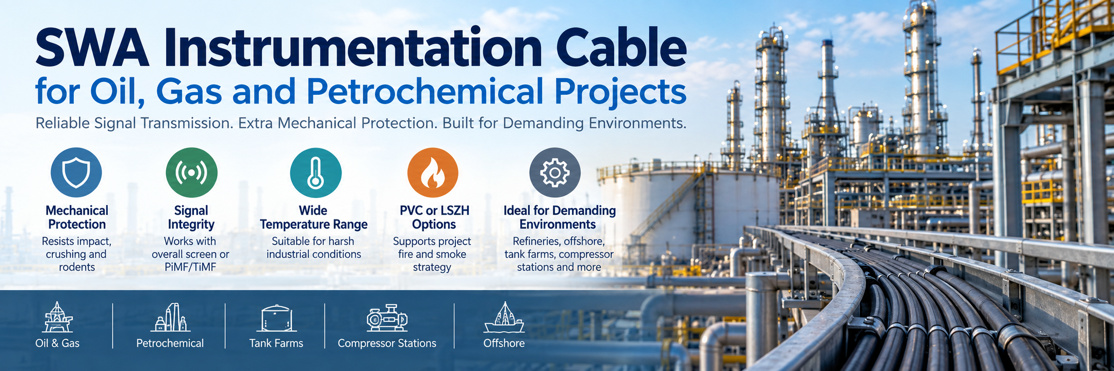
SWA Instrumentation Cable for Oil, Gas and Petrochemical Projects
Reading Time: 17 minutes
An SWA instrumentation cable combines low-level signal transmission with Steel Wire Armour to provide additional mechanical protection in demanding industrial routes. This combination is particularly relevant to oil, gas and petrochemical projects, where instrumentation cables can run through refineries, process units, tank farms, compressor stations, utility areas and other locations exposed to impact, crushing, rodents or heavy construction activity.
However, SWA should not be specified simply because a project is located in the oil and gas industry. Armour primarily addresses mechanical risk. Signal shielding, conductor grouping, capacitance, insulation, fire behaviour, chemical resistance and hazardous-area requirements remain separate engineering decisions.
Therefore, the correct cable should match both the instrumentation circuit and the physical installation environment. A protected control-room route may need screening but no armour, while an exposed outdoor tray can justify a screened, XLPE-insulated, steel-wire-armored construction.
Quick answer: Use SWA instrumentation cable where the route creates a credible risk of mechanical damage and the project permits metallic armour. Select the pair or triad configuration according to the instrument circuit, choose overall or individual PiMF/TiMF screening according to EMI and circuit-isolation requirements, and then specify PVC or LSZH materials according to the environmental and fire strategy. SWA does not replace the instrumentation screen and does not by itself make a cable suitable for hazardous areas, direct burial or fire-resistant applications.
SWA Instrumentation Cable at a Glance
| Project Requirement | Construction to Consider | Main Reason |
|---|---|---|
| Mechanical exposure | SWA instrumentation cable | Additional resistance to impact, crushing and external stress |
| Two-wire instrumentation circuit | Pair / TP construction | Matches typical two-conductor loop architecture |
| Three-wire instrumentation circuit | Triad / TT construction | Keeps three related conductors together |
| Moderate EMI | Overall-screened construction | Protects complete cable core against external interference |
| Sensitive multicircuit signals | PiMF / TiMF + overall screen | Adds circuit-to-circuit isolation |
| General industrial environment | PVC sheath where permitted | Practical industrial protection |
| Low-smoke / halogen-free requirement | LSZH / halogen-free construction | Supports project fire and smoke strategy |
| Outdoor route | UV-resistant outer sheath | Protects against long-term sunlight exposure |
| Hazardous area | Project-specified cable + approved installation system | Cable selection must follow the complete hazardous-area design |
The important principle is that SWA solves only one part of the specification.
Consequently, an engineer should not use the term “SWA instrumentation cable” as a substitute for defining the complete electrical, mechanical and environmental construction.
What Is an SWA Instrumentation Cable?
An SWA instrumentation cable is a signal or control cable that includes a layer of galvanized steel wires around the inner cable construction.
The instrumentation core can carry analogue or digital measurement and control signals between field devices and systems such as:
- DCS
- PLC
- SCADA
- Marshalling cabinets
- Remote I/O
- Safety systems
- Monitoring equipment
Meanwhile, the Steel Wire Armour provides additional mechanical reinforcement around that signal cable.
Depending on the product family, the complete construction can therefore include:
- Copper conductors
- PE, XLPE or PVC insulation
- Pairs, triads or layered cores
- Individual PiMF or TiMF screens
- Overall Al/PET screen
- Tinned-copper drain wire
- Inner sheath
- Galvanized steel wire armour
- PVC, PE or halogen-free outer sheath
Why Is SWA Used in Oil and Gas Instrumentation?
Oil and gas facilities can expose cable routes to significantly more mechanical risk than a conventional commercial building.
For example, instrumentation cables may pass through:
- Open cable trays
- Process units
- Pipe racks
- Tank farms
- Compressor stations
- Pump areas
- Loading terminals
- Utility plants
- Outdoor junction-box routes
- Underground infrastructure
Heavy construction activity can also continue during plant expansion or maintenance.
As a result, cables can face:
- Impact
- Crushing
- Abrasion
- Rodent attack
- Installation damage
- External mechanical loading
Steel wire armour provides an additional protective layer against these hazards.
SWA Does Not Replace Instrumentation Shielding
This distinction is critical.
SWA primarily provides mechanical protection.
The instrumentation screen primarily addresses electromagnetic interference and signal integrity.
Although a metallic armour layer can interact with electromagnetic fields, it should not be treated as a substitute for the cable’s dedicated foil or braid screening system.
Therefore, a typical screened SWA instrumentation cable may include both:
- Al/PET foil screen + drain wire
- Galvanized steel wire armour
Each layer has a different engineering purpose.
Typical SWA Instrumentation Cable Construction
A common industrial SWA instrumentation cable can follow this sequence:
| Layer | Typical Material | Function |
|---|---|---|
| 1. Conductor | Stranded copper | Carries instrumentation signal |
| 2. Insulation | XLPE, PE or PVC | Electrical insulation |
| 3. Pair / triad assembly | Twisted insulated conductors | Groups conductors by circuit |
| 4. Individual screen where required | Al/PET foil + drain wire | Pair-to-pair or triad-to-triad isolation |
| 5. Overall screen | Al/PET foil + drain wire | External EMI protection |
| 6. Inner sheath | PVC or halogen-free compound | Provides bedding beneath armour |
| 7. Armour | Galvanized steel wires | Mechanical reinforcement |
| 8. Outer sheath | PVC, LSZH or project-specific compound | Environmental and external protection |
However, the exact construction varies between product families.
For this reason, engineers should work from the actual datasheet rather than interpreting the cable code alone.
Why Is an Inner Sheath Used Beneath SWA?
The inner sheath provides a stable bedding layer for the steel wires.
Without suitable bedding, the armour would sit directly against more delicate cable components such as screens or assembled signal elements.
Therefore, the inner sheath can help:
- Maintain cable geometry
- Separate armour from screens
- Provide a smooth armour bedding
- Improve mechanical stability
- Protect the underlying cable core
After the armour is applied, the outer jacket then protects the complete cable from the installation environment.
What Does the SWA Layer Protect Against?
Steel Wire Armour can provide useful protection against several mechanical hazards.
Impact
Industrial sites can expose cable to tools, equipment, construction materials and accidental physical contact.
Therefore, SWA provides an additional mechanical barrier before an impact reaches the signal core.
Crushing
Cables can encounter compression in heavy cable trays, underground sections or industrial infrastructure.
Consequently, the steel-wire layer can improve resistance to external mechanical loading.
Rodents
Steel armour creates a strong physical barrier against rodent penetration.
However, actual suitability should still follow the complete cable construction and route risk.
Installation Damage
Long industrial cable pulls can expose a cable to abrasion and mechanical handling.
In addition, construction sites can remain active around the installed routes.
As a result, SWA can provide useful additional protection throughout both installation and service life.
When Is SWA Instrumentation Cable Unnecessary?
More armour does not automatically create a better instrumentation system.
For example, a cable inside:
- Protected control rooms
- Enclosed cabinets
- Dedicated indoor trays
- Protected conduits
- Low-risk technical spaces
may face very little mechanical exposure.
In that situation, an unarmored screened instrumentation cable can provide:
- Smaller outside diameter
- Lower weight
- Greater flexibility
- Easier termination
- Lower material cost
Therefore, SWA should solve a real mechanical requirement rather than serve as a default oil-and-gas specification.
SWA vs Unarmored Instrumentation Cable
| Characteristic | Unarmored | SWA |
|---|---|---|
| Mechanical protection | Basic cable construction | Additional steel-wire protection |
| Weight | Lower | Higher |
| Outside diameter | Smaller | Larger |
| Flexibility | Generally higher | Generally lower |
| Installation effort | Lower | Higher |
| Exposed industrial routes | May require additional pathway protection | Often more suitable |
| Protected control-room routes | Often sufficient | May be unnecessary |
Therefore, the installation route should determine whether armour adds genuine engineering value.
SWA vs SWB for Instrumentation Cables
ETK also manufactures instrumentation cables using Steel Wire Braid.
SWA and SWB both provide additional mechanical protection, but their structures differ.
SWA uses galvanized wires arranged as an armour layer. By contrast, SWB uses interwoven steel wires.
As a result, SWB can provide greater flexibility in some constructions, while SWA remains attractive for demanding fixed routes requiring robust mechanical protection.
However, neither should be selected only from the acronym.
Engineers should compare:
- Mechanical risk
- Bending radius
- Cable diameter
- Installation route
- Tensile requirements
- Project specification
Pair vs Triad SWA Instrumentation Cable
The armour does not determine whether the cable should use pairs or triads.
Instead, the instrument circuit makes that decision.
A pair contains two related conductors and commonly suits:
- Two-wire 4–20 mA loops
- Analogue transmitter circuits
- Two-conductor signal circuits
Meanwhile, a triad contains three conductors and can suit:
- Three-wire RTDs
- Three-wire transmitters
- Other three-conductor measurement circuits
Therefore, the correct sequence is:
Choose pair or triad from the circuit → choose screening → evaluate SWA from the mechanical route.
Overall-Screened SWA Instrumentation Cable
An overall-screened construction places a common metallic screen around the assembled signal core.
For example, a typical design can use:
- Tinned-copper drain wire
- Al/PET foil
- Inner sheath
- SWA
- Outer sheath
This architecture provides external electromagnetic protection while keeping the internal cable structure relatively straightforward.
Therefore, it can be suitable where individual circuits do not require separate screens.
PiMF and TiMF SWA Instrumentation Cable
More demanding systems can use individual screens around each pair or triad.
PiMF provides an individual foil screen around each pair.
Meanwhile, TiMF provides an individual foil screen around each triad.
Afterward, manufacturers can assemble the screened elements and apply another overall screen before the inner sheath and SWA.
Consequently, the construction can provide:
- Pair-to-pair or triad-to-triad isolation
- External EMI screening
- Mechanical SWA protection
These are three distinct functions within one cable.
Overall Screen vs PiMF/TiMF for Refineries
| Requirement | Overall Screen | PiMF / TiMF + Overall Screen |
|---|---|---|
| External EMI protection | Yes | Yes |
| Individual circuit isolation | Limited | Higher |
| Cable diameter | Generally smaller | Generally larger |
| Termination complexity | Lower | Higher |
| Material content | Lower | Higher |
| High-density sensitive circuits | Project-dependent | Often attractive |
Therefore, individually screened construction should be justified by signal requirements rather than automatically added to every SWA cable.
XLPE Insulation in SWA Instrumentation Cable
XLPE is widely used in demanding instrumentation constructions because it provides strong electrical characteristics together with useful thermal and mechanical performance.
Compared with conventional thermoplastic insulation, XLPE can provide advantages involving:
- Temperature capability
- Insulation resistance
- Mechanical stability
- Electrical performance
For this reason, ETK uses XLPE in several RE-2X SWA instrumentation families.
However, XLPE alone does not define the cable’s screening, armour or fire performance.
PVC-Insulated SWA Instrumentation Cable
PVC insulation remains available in instrumentation constructions where the project and electrical requirements permit it.
For example, RE-Y(St)YSWAY combines PVC insulation, an overall Al/PET screen, PVC inner sheath, galvanized steel wire armour and a UV-resistant PVC outer sheath.
Therefore, PVC-based constructions can remain practical for conventional industrial applications where halogen-free performance is not required.
PVC vs LSZH Outer Sheath
The sheath system should follow the actual fire and environmental strategy.
PVC
PVC can provide:
- Good general mechanical durability
- Practical industrial performance
- Abrasion resistance
- Cost efficiency
However, conventional PVC produces smoke and halogen-containing combustion products during fire.
LSZH / Halogen-Free
Halogen-free sheath systems can reduce smoke density and corrosive halogen-related gases compared with conventional halogenated materials.
Therefore, they can be particularly relevant in:
- Enclosed process buildings
- Tunnels
- Control buildings
- Offshore structures
- Evacuation-sensitive locations
Nevertheless, LSZH does not automatically mean fire resistant.
RE-2X(St)YSWAY vs RE-2X(St)HSWAH
These two constructions illustrate how SWA can remain constant while the sheath system changes.
| Characteristic | RE-2X(St)YSWAY | RE-2X(St)HSWAH |
|---|---|---|
| Insulation | XLPE | XLPE |
| Screening | Overall screen | Overall screen |
| Inner sheath | PVC | Halogen-free |
| Armour | Galvanized SWA | Galvanized SWA |
| Outer sheath | PVC | Halogen-free |
| Main selection distinction | Conventional industrial construction | Halogen-free fire/smoke strategy |
Therefore, the armour designation alone does not define the fire-material behaviour of the cable.
RE-Y(St)YSWAY vs RE-2X(St)YSWAY
The difference between these families begins with the insulation system.
RE-Y… constructions use PVC-based insulation.
RE-2X… constructions use XLPE insulation.
Both can incorporate:
- Instrumentation screening
- PVC inner sheath
- SWA
- Outdoor PVC outer sheath
Consequently, engineers should not select between them simply because both contain SWA.
The electrical, thermal and project requirements should determine the insulation system.
ETK SWA Instrumentation Cable Families
| Construction | Key Feature | Typical Selection Logic |
|---|---|---|
| RE-Y(St)YSWAY | PVC insulation + overall screen + SWA + PVC sheath | Conventional armored instrumentation route |
| RE-2X(St)YSWAY | XLPE insulation + overall screen + SWA + PVC sheath | Higher-performance XLPE construction |
| RE-2X(St)YSWAY PiMF/TiMF | Individual screens + overall screen + SWA | Greater circuit isolation in mechanically demanding routes |
| RE-2X(St)HSWAH | XLPE + overall screen + SWA + halogen-free sheath | Mechanical protection with halogen-free materials |
| RE-2X(St)HSWAH PiMF/TiMF | Individual screens + overall screen + SWA + halogen-free sheath | High circuit isolation + mechanical protection + halogen-free construction |
This table shows why “SWA instrumentation cable” is only the starting point.
Screening, insulation and sheath architecture still need to be selected separately.
SWA Instrumentation Cable for 4–20 mA Loops
Two-wire 4–20 mA circuits commonly use twisted pairs.
If the cable route is mechanically exposed, the project can combine the pair-based instrumentation design with SWA.
For example, the cable can connect:
- Pressure transmitters
- Flow transmitters
- Level transmitters
- Temperature transmitters
- Control-system I/O
However, the mechanical need for armour remains separate from the electrical loop architecture.
SWA Instrumentation Cable for RTD Circuits
Three-wire RTD circuits can use triad-based instrumentation cable.
Where the route requires additional mechanical protection, that triad construction can also include SWA.
Meanwhile, individually screened TiMF designs can provide additional circuit isolation if the project requires it.
Therefore, a typical design sequence can become:
3-wire RTD → triad → TiMF if needed → overall screen if specified → SWA if mechanically required.
SWA Cable for DCS and PLC Systems
DCS and PLC installations often aggregate many field circuits into junction boxes and marshalling systems.
Therefore, multicircuit instrumentation cables can significantly reduce the number of individual cables required across a large plant.
Depending on the signal mix, the project can use:
- Multipair cable
- Multitriad cable
- Overall-screened cable
- PiMF/TiMF cable
- SWA versions of each construction
As a result, one cable family can serve many different field architectures while maintaining the required mechanical protection.
SWA Instrumentation Cable in Refineries
Refineries combine sensitive instrumentation with heavy industrial infrastructure.
Cable routes can pass near:
- Compressors
- Pumps
- Motors
- Variable-frequency drives
- Power distribution
- Pipe racks
- Process vessels
Therefore, the cable specification may need to address both EMI and mechanical risk.
An overall or individually screened instrumentation core can protect signal integrity, while SWA can provide additional mechanical protection around the complete cable.
SWA Instrumentation Cable in Petrochemical Plants
Petrochemical plants can contain long cable routes between field instruments and centralized control systems.
In addition, plant expansions and equipment modifications can increase the probability of accidental cable damage over the facility life.
For this reason, SWA can be useful on exposed fixed routes.
However, the project should also define:
- Chemical exposure
- Oil resistance
- UV resistance
- Temperature range
- Fire performance
- Screening
- Intrinsic-safety parameters
Armour alone does not address these requirements.
SWA Instrumentation Cable for Tank Farms
Tank farms can create long outdoor instrumentation routes between tanks, field devices and control infrastructure.
Consequently, cables may experience:
- UV exposure
- Temperature variation
- Rodent risk
- Mechanical maintenance activity
- Outdoor moisture
Therefore, a suitable outdoor sheath becomes as important as the SWA layer.
The complete product should be selected for the actual environmental conditions rather than relying only on the presence of steel armour.
SWA Instrumentation Cable for Compressor and Pump Stations
Compressor and pump stations contain rotating machinery and power equipment that can create both mechanical and electromagnetic challenges.
For this reason, instrumentation routes may require:
- Overall or individual screening
- Appropriate routing separation
- SWA mechanical protection
- Oil-resistant materials where specified
- Outdoor UV resistance
However, increasing armour does not improve the intrinsic EMI rejection of the instrumentation pair or triad.
Dedicated screening and installation practice remain essential.
SWA Instrumentation Cable for Offshore Platforms
Offshore installations can impose particularly demanding requirements on cable systems.
Projects may require combinations of:
- Mechanical armour
- Low-smoke materials
- Halogen-free construction
- Oil resistance
- Fire performance
- Marine or offshore approvals
- UV resistance
Therefore, a generic land-based SWA instrumentation cable should not automatically be assumed suitable offshore.
The actual platform specification and approval requirements should determine the complete product.
SWA Instrumentation Cable and Hazardous Areas
Oil, gas and petrochemical facilities contain hazardous-area zones where flammable gases or vapours may be present.
However, SWA itself does not make a cable “explosion proof.”
This distinction is important.
The hazardous-area installation normally depends on the complete system, including:
- Equipment protection concept
- Cable glands
- Sealing arrangements
- Grounding and bonding
- Intrinsic-safety design where applicable
- Local regulations
- Project specifications
Therefore, cable selection should follow the approved hazardous-area engineering philosophy.
SWA Instrumentation Cable in Intrinsically Safe Circuits
Intrinsic safety limits the electrical energy that can enter a hazardous area.
The cable can contribute capacitance and inductance to the complete loop.
Consequently, engineers may need to review:
- Mutual capacitance
- Conductor-to-screen capacitance
- Inductance
- Conductor resistance
- Loop length
- Barrier parameters
- Field-device parameters
SWA primarily provides mechanical protection and does not establish intrinsic-safety compliance.
Does SWA Affect Signal Integrity?
The primary signal-integrity features remain conductor geometry and dedicated screening.
For example:
- Twisting helps control induced noise
- Individual screens help isolate circuits
- Overall screens help reduce external interference
- Correct grounding helps the screen operate as intended
Meanwhile, SWA protects the complete construction against mechanical damage that could eventually affect cable performance.
Therefore, SWA protects signal reliability indirectly through physical protection rather than replacing the signal-screening system.
SWA Armour Grounding and Bonding
SWA introduces a conductive metallic layer along the cable route.
Consequently, the project may need to define bonding and grounding arrangements for the armour.
Important considerations can include:
- Building entry
- Hazardous-area gland systems
- Potential differences between locations
- Earth continuity
- Plant grounding philosophy
- Local electrical regulations
However, instrumentation-screen grounding and SWA grounding should not automatically be treated as the same connection.
The signal-screen termination philosophy can differ from the mechanical-armour bonding arrangement.
SWA and Instrumentation Screen Grounding Are Different
This point deserves particular attention.
An instrumentation foil screen exists primarily to control electrical interference.
SWA exists primarily for mechanical protection and forms a large conductive metallic layer.
Therefore, the engineering design may treat:
- Individual pair/triad drain wires
- Overall-screen drain wire
- SWA
as different conductive systems with different termination requirements.
Installers should follow the approved project grounding drawings rather than combining them arbitrarily.
Can SWA Instrumentation Cable Be Installed Outdoors?
Yes, when the complete product has an appropriate outdoor sheath.
However, steel armour alone does not establish outdoor suitability.
The outer jacket should provide the required:
- UV resistance
- Moisture resistance
- Temperature performance
- Chemical resistance where applicable
For this reason, ETK’s relevant outdoor SWA instrumentation constructions use UV-resistant outer sheaths.
Can SWA Instrumentation Cable Be Directly Buried?
Some SWA instrumentation cables may be designed for underground or direct-burial use, but this should not be assumed from the armour acronym alone.
A direct-burial specification can also require:
- Water protection
- Appropriate outer sheath
- Crush resistance
- Rodent protection
- Chemical resistance
- Suitable mechanical test values
Therefore, the actual datasheet and project specification should confirm burial suitability.
Can SWA Instrumentation Cable Run in Cable Trays?
Yes, fixed cable trays are a common industrial application.
SWA can be particularly useful where the tray is exposed to maintenance activity, impact or other mechanical hazards.
However, engineers should still consider:
- Tray loading
- Cable weight
- Bending radius
- Gland size
- Cable spacing
- EMC separation from power cables
Consequently, armour does not eliminate the need for good cable-route design.
Why Bending Radius Matters with SWA
Steel armour increases cable stiffness.
Therefore, an SWA cable normally requires more installation space than a comparable unarmored cable.
Problem areas can include:
- Junction-box entries
- Cable trays
- Vertical risers
- Control-room transitions
- Gland plates
For example, ETK publishes a 7.5 × D bending radius for RE-2X(St)HSWAH.
Consequently, designers should review actual product dimensions before finalizing tray and gland layouts.
Conductor Size in SWA Instrumentation Cable
Steel armour does not determine conductor cross-section.
The conductor size should follow the electrical loop requirement.
Common ETK instrumentation options include:
- 0.50 mm²
- 0.75 mm²
- 1.00 mm²
- 1.50 mm²
- 2.50 mm²
For example, ETK currently publishes these sizes across relevant RE-2X SWA constructions.
Selection should consider:
- Loop resistance
- Route length
- Voltage drop
- Signal type
- Device current
- Project requirements
SWA Instrumentation Cable Temperature Range
Temperature capability depends on insulation and sheath materials.
Therefore, engineers should not infer operating temperature from the SWA layer.
For example, ETK specifies a −30°C to +90°C operating range for its RE-2X(St)HSWAH construction.
However, other products can use different material systems and therefore different ratings.
The actual datasheet should always govern selection.
Fire Performance in SWA Instrumentation Cable
SWA does not make a cable flame retardant or fire resistant.
Those characteristics come from the insulation, sheath system and tested cable design.
Depending on the product, projects can require:
- IEC 60332 flame-propagation performance
- IEC 61034 smoke-density performance
- IEC 60754 halogen and corrosive-gas performance
- Other project-specific fire requirements
For example, ETK’s halogen-free RE-2X(St)HSWAH family lists IEC 61034-2, IEC 60754-1/-2 and IEC 60332 testing alongside its SWA construction.
Flame Retardant vs Fire Resistant SWA Instrumentation Cable
These terms should not be confused.
Flame retardant relates primarily to limiting flame propagation.
Fire resistant relates to maintaining a required circuit function during fire for a defined test period.
Therefore, an SWA instrumentation cable that passes a flame-propagation test should not automatically be described as fire resistant.
If circuit integrity is required, the project must specify the appropriate fire-resistant cable design and test standard separately.
Chemical and Oil Resistance
Refineries and petrochemical facilities can expose cables to hydrocarbons, lubricants and process chemicals.
However, a generic SWA construction does not automatically resist every substance.
For this reason, the RFQ should identify:
- Expected chemical
- Exposure duration
- Operating temperature
- Required test standard
- Required outer-sheath compound
The manufacturer can then confirm whether the proposed cable provides the necessary compatibility.
SWA Instrumentation Cable Standards
BS EN 50288-7 remains an important reference for multi-element metallic instrumentation and control cables used for analogue and digital signal transmission.
The standard covers mechanically robust instrumentation/control cable constructions and allows screening, optional armouring and environmental or moisture-protection layers.
Importantly, the standard framework does not mean every cable uses the same insulation, screen, armour or sheath.
Therefore, a complete project specification should still define:
- Conductor size
- Pair or triad arrangement
- Screening
- SWA requirement
- Insulation
- Sheath
- Fire behaviour
- Environmental performance
A Note on BS 5308 / PAS 5308 References
Older oil, gas and petrochemical specifications frequently reference BS 5308-style instrumentation constructions.
However, BSI withdrew PAS 5308-1:2009 and PAS 5308-2:2009 in April 2024. The current BS EN 50288-7 remains the relevant European instrumentation/control cable specification.
Therefore, purchasing teams should check whether an older project specification needs updating rather than copying legacy references automatically.
How to Select an SWA Instrumentation Cable
| Question | If Yes | Selection Consideration |
|---|---|---|
| Does the route face mechanical damage? | Yes | Consider SWA |
| Does the circuit use two conductors? | Yes | Pair / TP construction |
| Does the circuit use three conductors? | Yes | Triad / TT construction |
| Is individual circuit isolation required? | Yes | PiMF / TiMF |
| Is only external EMI protection required? | Yes | Overall screen may be sufficient |
| Is LSZH required? | Yes | Halogen-free SWA construction |
| Is the route outdoors? | Yes | UV-resistant outer sheath |
| Is the route hazardous? | Yes | Follow approved hazardous-area design and cable-gland requirements |
| Is direct burial required? | Yes | Confirm full burial construction, not SWA alone |
| Is oil/chemical exposure expected? | Yes | Specify required compound resistance |
Common Mistakes When Specifying SWA Instrumentation Cable
1. Assuming Every Oil and Gas Cable Needs SWA
Protected routes may not require additional steel armour.
2. Using SWA as an EMI Screen
SWA primarily provides mechanical protection. Dedicated instrumentation screens should address signal interference.
3. Assuming SWA Makes the Cable Explosion Proof
Hazardous-area compliance depends on the complete installation system and protection concept.
4. Ignoring Pair vs Triad Requirements
The field-device circuit should determine conductor grouping before armour is considered.
5. Specifying PiMF/TiMF for Every Circuit
Individual screening can increase diameter, weight and termination complexity when it is unnecessary.
6. Assuming SWA Means LSZH
SWA describes armour. PVC and halogen-free sheath systems are separate choices.
7. Assuming SWA Means Fire Resistant
Fire resistance requires a specific cable design and circuit-integrity test.
8. Assuming SWA Automatically Means Outdoor
Outdoor suitability also depends on the outer sheath and environmental specification.
9. Assuming SWA Automatically Means Direct Burial
Burial suitability requires confirmation of the complete cable design.
10. Ignoring Cable Weight and Bending Radius
Steel armour can materially increase handling and pathway requirements.
11. Ignoring Armour Grounding
Metallic SWA can introduce bonding and grounding requirements.
12. Connecting Instrument Screens and Armour Arbitrarily
The signal-screen and armour grounding philosophies can be different.
13. Choosing Insulation Only from the Cable Code
Electrical and temperature requirements should determine PVC, PE or XLPE selection.
14. Assuming LSZH Is Suitable for Every Outdoor Environment
Fire performance and outdoor environmental resistance are separate material requirements.
15. Ignoring Chemical Exposure
Oil and gas routes can require specific compound compatibility beyond generic industrial performance.
16. Reusing Legacy Standards Without Checking Status
Older project specifications may reference withdrawn standards and should be reviewed against current requirements.
What Should Be Included in an SWA Instrumentation Cable RFQ?
A request that states only “SWA instrumentation cable for refinery” leaves most of the engineering specification unresolved.
A useful RFQ should define:
- Number of cores, pairs or triads
- Pair / triad requirement
- Conductor cross-section
- Conductor class
- Conductor material
- Insulation material
- XLPE, PE or PVC requirement
- Overall screen requirement
- PiMF / TiMF requirement where applicable
- Drain-wire construction
- Maximum conductor resistance
- Maximum capacitance
- Inductance where relevant
- Operating voltage
- Intrinsic-safety electrical parameters where required
- Inner sheath material
- SWA requirement
- Armour material and construction
- Outer sheath material
- PVC or LSZH requirement
- UV resistance
- Oil resistance
- Chemical resistance
- Operating temperature
- Installation temperature
- Minimum bending radius
- Outdoor or indoor use
- Direct-burial requirement where applicable
- Hazardous-area installation requirements
- Flame-retardancy requirement
- Smoke-density requirement
- Halogen-free requirement
- Fire-resistance requirement if applicable
- Applicable EN, IEC or customer standard
- Cable marking
- Drum length
- Certificates
- Routine and type-test documentation
As a result, the manufacturer can quote a construction that solves the actual project requirement rather than simply adding SWA to a generic instrumentation cable.
ETK Kablo SWA Instrumentation Cable Solutions
ETK Kablo manufactures SWA instrumentation cable constructions for oil, gas, petrochemical, power, mining, tunnel, industrial and infrastructure projects.
The portfolio includes overall-screened and individually screened designs with different insulation and sheath systems.
RE-Y(St)YSWAY provides a PVC-insulated, overall-screened and steel-wire-armored construction for conventional industrial applications.
Meanwhile, RE-2X(St)YSWAY uses XLPE insulation together with overall screening, PVC inner and outer jackets and galvanized steel wire armour.
For applications requiring greater circuit-to-circuit isolation, RE-2X(St)YSWAY-PiMF/TiMF adds individual pair or triad screens before the overall screen and SWA.
Where the project requires halogen-free materials, RE-2X(St)HSWAH combines XLPE insulation, overall screening, halogen-free inner and outer jackets and galvanized steel wire armour. ETK also manufactures PiMF/TiMF variants of this construction for projects requiring both individual signal-element shielding and SWA mechanical protection.
Therefore, the appropriate ETK solution should be selected by separating four questions: circuit architecture, electromagnetic environment, mechanical exposure and environmental/fire requirements.
Frequently Asked Questions
What is an SWA instrumentation cable?
An SWA instrumentation cable is a low-level signal or control cable that includes Steel Wire Armour around the cable core to provide additional mechanical protection.
What does SWA mean?
SWA means Steel Wire Armour. Galvanized steel wires form a protective mechanical layer around the cable.
Why is SWA used in oil and gas projects?
SWA can protect instrumentation cables against impact, crushing, rodents and other mechanical risks common in exposed industrial routes.
Does every oil and gas instrumentation cable need SWA?
No. Armour should follow the mechanical conditions of the route. Protected indoor or conduit installations may not require it.
Does SWA provide EMI protection?
The cable’s dedicated foil or braid screen should provide the primary instrumentation EMI protection. SWA primarily addresses mechanical damage.
Can SWA instrumentation cable use PiMF?
Yes. Individually screened pairs can be combined with an overall screen and Steel Wire Armour.
Can SWA instrumentation cable use TiMF?
Yes. Individually screened triads can also be combined with an overall screen and SWA.
What is the difference between PiMF/TiMF and SWA?
PiMF and TiMF describe individual signal-element screening. SWA describes the mechanical steel-wire protection around the complete cable.
Can SWA instrumentation cable be LSZH?
Yes. SWA can be combined with halogen-free inner and outer sheath systems, such as ETK’s RE-2X(St)HSWAH constructions.
Is SWA instrumentation cable fire resistant?
Not automatically. SWA provides mechanical protection. Fire resistance requires a cable specifically designed and tested for circuit integrity during fire.
Is SWA instrumentation cable flame retardant?
It can be when the complete cable materials and construction meet the required flame-propagation tests. Armour alone does not provide that classification.
Can SWA instrumentation cable be installed outdoors?
Yes, when the complete cable includes an appropriate UV- and weather-resistant outer sheath.
Can SWA instrumentation cable be directly buried?
Some constructions can be suitable, but direct-burial suitability should be confirmed from the actual product and project specification rather than assumed from SWA alone.
Does SWA need grounding?
Steel armour can introduce bonding or grounding requirements. The arrangement should follow the plant’s electrical and hazardous-area grounding philosophy.
Should the instrumentation screen and SWA be grounded together?
Not automatically. Signal-screen termination and armour bonding can serve different purposes and should follow the approved project grounding design.
What is the difference between RE-2X(St)YSWAY and RE-2X(St)HSWAH?
Both can use XLPE insulation, overall screening and SWA. RE-2X(St)YSWAY uses PVC sheath materials, while RE-2X(St)HSWAH uses halogen-free inner and outer sheath systems.
What is the difference between RE-Y(St)YSWAY and RE-2X(St)YSWAY?
RE-Y(St)YSWAY uses PVC insulation, while RE-2X(St)YSWAY uses XLPE insulation. Both can use overall screening, PVC sheath systems and Steel Wire Armour.
Which SWA instrumentation cable is best for a refinery?
There is no universal best construction. The correct cable depends on circuit type, EMI environment, mechanical exposure, fire strategy, outdoor conditions, chemical exposure and project standards.
Is SWA cable suitable for 4–20 mA loops?
Yes. A screened pair-based SWA instrumentation construction can carry 4–20 mA loops when the cable’s electrical parameters meet the circuit requirements.
Can SWA cable be used for 3-wire RTDs?
Yes. A triad-based SWA instrumentation cable can support three-wire RTD circuits where its conductor and electrical characteristics meet the measurement-system requirements.
Which standard covers instrumentation cables?
BS EN 50288-7 is an important current reference for multi-element instrumentation and control cables used for analogue and digital signal transmission and allows screened, armored and environmentally protected constructions.
Conclusion
An SWA instrumentation cable provides a practical way to combine precision signal transmission with additional mechanical protection in oil, gas and petrochemical projects.
However, Steel Wire Armour should never become the starting point for the entire cable specification.
First, the field circuit determines whether the cable needs pairs, triads or another conductor arrangement. Next, the electromagnetic environment determines whether an overall screen or PiMF/TiMF individual screening is appropriate.
Afterward, the installation route determines whether Steel Wire Armour provides useful mechanical protection against impact, crushing, rodents or other physical risks.
Meanwhile, insulation and sheath systems address separate requirements. XLPE can provide strong electrical and thermal performance, while PVC and halogen-free sheath options serve different environmental and fire strategies.
Hazardous-area, intrinsic-safety, oil-resistance and direct-burial requirements also need independent engineering review. SWA alone does not make a cable explosion proof, intrinsically safe, fire resistant or suitable for every underground environment.
For engineers and purchasing teams, the most reliable approach is therefore to define the signal circuit first, screening architecture second, mechanical exposure third, and finally the insulation, sheath, environmental and fire-performance requirements needed by the actual oil, gas or petrochemical installation.
Benzer yazılar
EN 50288-7 Instrumentation Cables Explained
EN 50288-7 cable specifications are widely used for instrumentation and control systems that transmit analogue or digital signals betwe...
PiMF vs TiMF Instrumentation Cable Explained
Understanding PiMF vs TiMF cable construction is important when an instrumentation system carries multiple low-level analogue or digita...
Instrumentation Cable Pair vs Triad: Which Should You Use?
Choosing between an instrumentation cable pair vs triad should begin with the electrical circuit rather than the cable construction. A ...
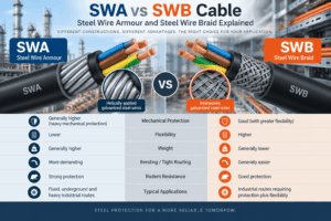
SWA vs SWB Cable: Steel Wire Armour and Steel Wire Braid Explained
Choosing between SWA vs SWB cable requires understanding how two different steel protection systems affect mechanical strength, flexibi...
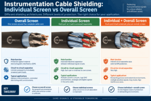
Instrumentation Cable Shielding: Individual Screen vs Overall Screen
Instrumentation cable shielding plays a critical role in protecting low-level analogue and digital signals from electromagnetic interfe...
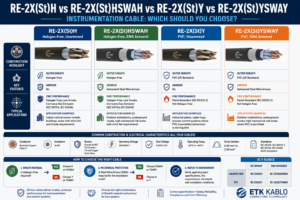
RE-2X(St)H vs RE-2X(St)HSWAH vs RE-2X(St)Y vs RE-2X(St)YSWAY: Which Should You Choose?
Choosing the right RE-2X(St) instrumentation cable is not simply a matter of comparing four similar product codes. RE-2X(St)H, RE-2X(St...
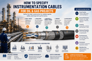
How to Specify Instrumentation Cables for Oil & Gas Projects
Selecting oil and gas instrumentation cables requires much more than choosing a conductor size and adding a screen. Refineries, petroch...


